Here I will be explaining my process of modelling and UV mapping my Mantel Clock model.

I started the model off by placing down the biggest shapes from the case of the clock, and the actual clock. At first I made these shapes with 20+ sub divisions so that I had enough edges to work with to sculpt into the shape as seen in the reference. (I would soon change these shapes later) This was the technique I used in both the vase challenge and the table challenge.
Source: Weekly Modelling Challenges – Week 1 – Vase / Jug modelling challenge, Week 2 Table modelling challenge.

As done before for the clock, I placed down a cylinder shape, copied and pasted it, made the copy smaller and clashed it with the original shape to extrude a part in the middle for the face of the clock, with the boolean – difference tool.

I made sure to try keep each object in the same position of the scene, and to follow the measurements I decided on to give the clock a natural proportion.
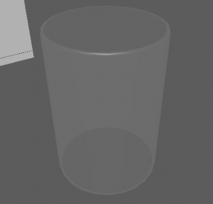
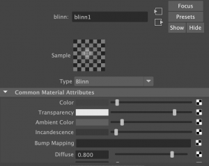
Here I added a hollow cylinder shape to create the glass pane. Immediately I assigned this cylinder a new material (blinn) so that I could work with designing a glass material. I altered the settings such as the colour, transparency and specular shading to give the glass effect.
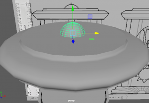
After these, I started to add in little details. The bell on top was a simple sphere that I cut in half and placed on the top of the clock.
I added hour and minute hands in the same design as my reference, in the shape of shining diamond stars. I used a thin cube and used the mutli-cut tool that adds divisions to scale the shape.
![]()

I also made multiple roman numerals for the numbers on the clock. I followed a sheet that helped me with each numeral and I added them onto the face of the clock.

I made the 1, 5 and 10 separately and then copy – pasted how many was needed for each other number.
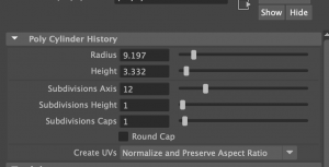
As I said before, I was going to restart the base shapes I made at the start. I wanted to start them with a more simpler style and it would eventually become easier to work on as it had been before hand etc. the many divisions was too much to work on, the position and scale got confusing.

I remade them and kept the divisions at 12 each. I eventually made many more objects have 12 divisions as they fit well when positioned together etc. the rim around the glass pane, the top and bottom base, and the pillars.

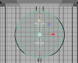
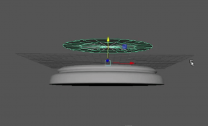
I then went on to make the sun inside the clock. This took many tries to find the right style but I found I could use a low poly sphere (shaped like an oval from the side) and added similar shaped cones around the base to make the sun rays.

It was a challenge to get the rays in perfect place from its opposite as best as I could. I made use of the translate settings on the right of my screen to determine where they are placed. I made sure the sun base was reset in the middle of the clock first, then I worked on the rays. I also worked on the degrees settings to flip the rays around when I copy – pasted them to the other side.

At this part, this is what my clock looks like so far, along with what is included in the outliner.
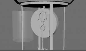
Here I was working on the back of the clock, so that in reality, the clock inside would work like a pendulum clock with the sun attached to a rod, connected to the back/middle of the clock, being run by moving gears.
I made the cogs with the Torus shape, turned down the divisions and rotated the object to have faces pointing horizontally. I also selected faces around the side, leaving a space between each, then extruded them outwards to make the shapes of a gear.![]()

Once my shapes were made, I went onto smoothing most of the shapes to give them a nicer, finished look for the end result. As you can see beforehand, the shapes such as the hour hand is quite boxy.

Here you can see the smooth setting I clicked on to give my shapes this look. The hour hand now looks more realistic for the look of a clock.

I continued doing this with objects such as the sun, rods in the clock, the glass pane and the top and bottom base.
The sun smoothed pretty well, however for the cones, I had to add an extra edge loop on the bottom of the cone, where it sits on the sun base, to allow the smoothing feature to work better.
Before I did this, the smoothing made the cones look like a circle with two points on the top and bottom.
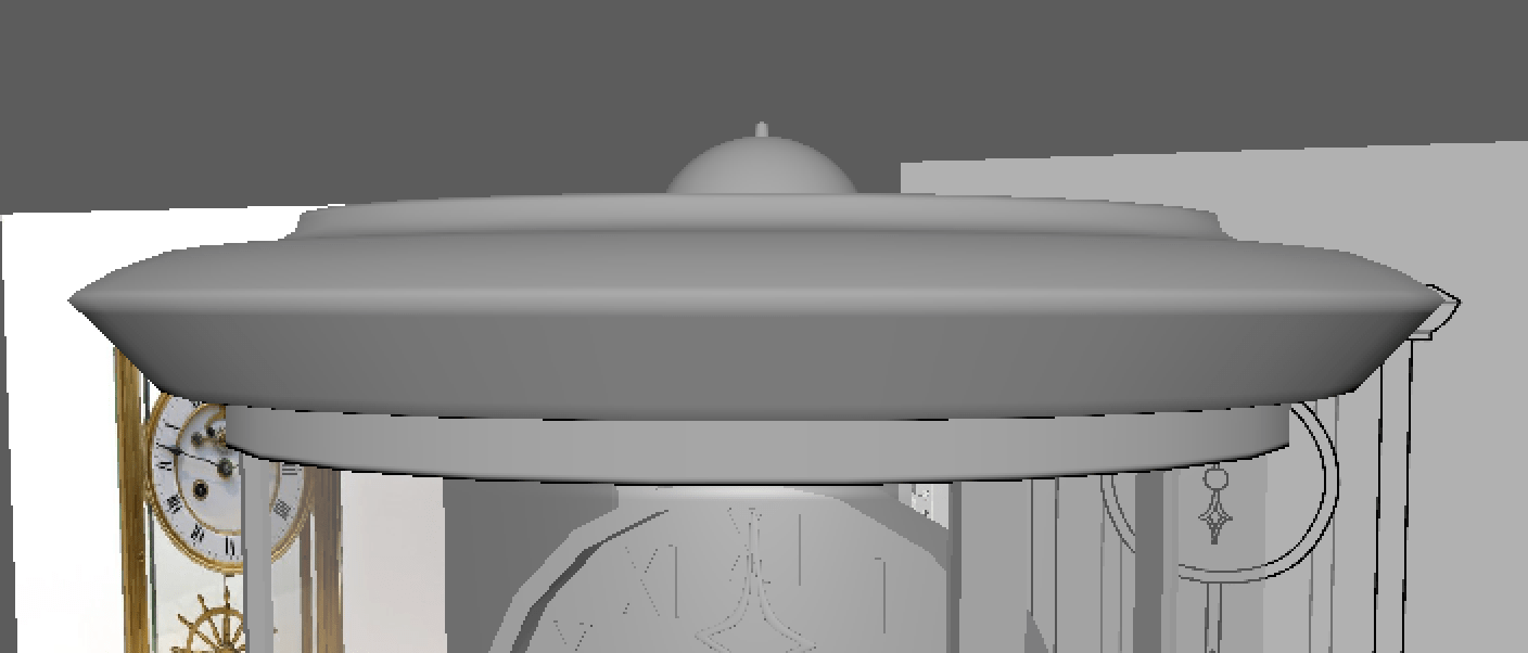
Here are the base shapes when they are smoothed.

During this time, I made sure to add a stand for the bottom of the clock like I designed in my reference. I quickly cut a cylinder shape in half,
and scaled them to the shape of the base and placed beneath the clock.
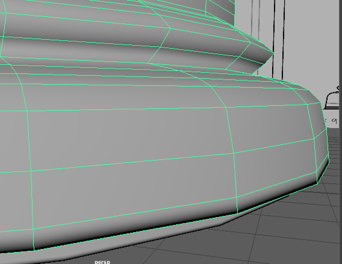
As I mentioned before for the cones, adding some more edge loops with the multi-cut tool to the edge of a face etc. like the last edge loop in the object to the left, will emphasise the edge more than it usually would when smoothed.
After all this, I started to UV map the clock model.

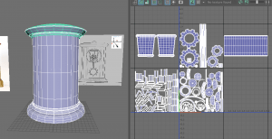
Before I got Henry’s help, which I asked for later on, I was mainly using the planar tool to plot each UV part of the object onto the UV editor. I made use of the x, y and z axis to place them down at a position that presents the parts well.
![]()

I had made sure that my UV parts were positioned well and not being stretched like I had seen on the checkered texture. However, around this time, I could have been unfolding the UVs more rather than making them perfectly straight.

I did not know this at the time, but I made the mistake of placing UVs across two UV islands which would end up confusing the UV map altogether. I would eventually fix this problem later on.
 At the time, I did think that separating each part of the model into separate UV islands was the right idea, however I learnt that we are able to group all the parts together into one UV island that will share the same material attribute.

I decided to contact my tutor Henry for some help because when I was exporting the model, It was not working properly on Substance, so I couldn’t move forward with my work. Henry was a great help and pointed out the two biggest errors in my model, that I went onto fix. They were the Mesh and the UV.
In the mesh, I had accidentally produced extra faces/edges inside the top and bottom base of the clock. They had caused non-manifold geometry. All I had to do was zoom inside the part and delete these faces and edges that were effecting the mesh.
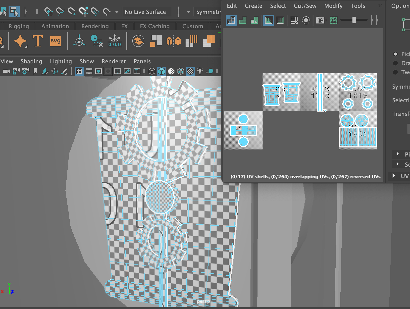
The next error was the UV mapping. I learnt from Henry that I had not used an option that would have helped me determine which UVs were flipped, not unfolded etc. By clicking to where the arrow is pointing on the left, I would get the red and blue highlighting on the right.


Henry recommended that I use the UV editing workspace that provided me with many more options and easy access to all the UV features. I found this very helpful during the UV process.

As you can see, there were many parts highlighted in red, so there was lots to do. I noticed the sun was not UV mapped well enough so I started with it. I cut around the edge base, and both sides of the cone, to let it unfold, giving me two triangles and a circle base on the UV editor. I did this for every triangle, then I cut in half the sun base and also unfolded it.
![]()
![]()

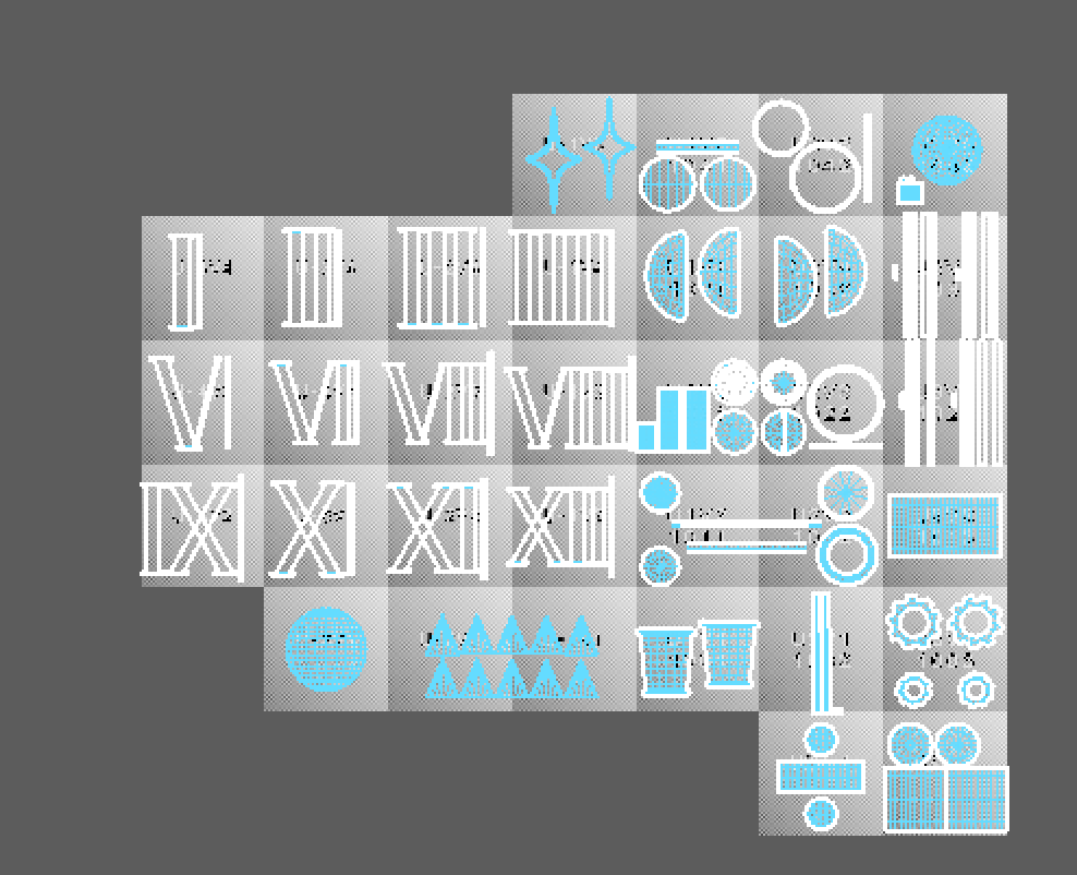
I went back to the roman numerals as they were not unfolded properly. I selected the whole number, unfolded them and clicked layout to organise them in their UV Islands. Once I had finished them all I brought them all into one UV island as they will all share the same texture.
I had many more parts to flip, unfold and layout. However I was able to complete the UV mapping. Here you can see I organised the parts into what texture they will be sharing. Etc. the case, the clock, the sun and the hour/minute hands will all have a gold/brass material. However, this will cause a little problem again in Substance later on. I would have to group every part into the one UV island to fix the problem. (This is explained in ‘Texturing’)
Before After

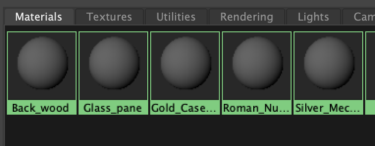 As soon as I finished all this, I cleaned up my model just in case I missed anything. I gave every group of parts a lambert material that was named after the texture look I wanted to make for it. After this I was ready to export and bring my model into Substance Painter.