Category: Weekly Modelling Challenges
Week 4 – Texturing
This week for the weekly Modelling Challenges we looked over texturing. Texturing is the placement of material, colour or pattern onto an object or model. We were required to test out a program called Substance Painter along with working in Maya. Substance Painter is known as the place to build and structure textures onto already-made models.
Source: Week 04 – Texturing – Substance painter intro.mp4, Breaking maps for smart materials.mp4, export maps from substance to maya or sketchfab.mp4
First off, we were given a UV mapped hard surface model ready to texture. We jumped onto Substance painter during class to get used to the program and then attempted to place texture onto our object.
Source: Substance Painter

Before I do anything else, we bake our ID maps. I scroll down at the right column of menus to find texture set settings-bake mesh maps, change mesh size and tick ‘Use low poly mesh as high poly mesh’, to help keep the mesh the same. Then change the ID setting ‘Colour source’ to ‘Mesh ID/Polygroup’ To help generate an ID map based on the seperate models in the one file.
 Once ‘Bake selected textures’ is clicked, we get multiple mesh
informations, and each one helps determines a seperate feature e.g. shadows, edges, each model, thickness.
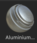
Now I could pick a smart material to place onto the model. I chose ‘Aluminium Brushed Worn’ to test out first, and just left click and dragged onto the model to place.
 what I could also do is place other materials. I did this by dragging
 another material onto the model (Chrome Blue Tint) , right click the layer it comes from, select add mask with colour selection, turn in ID map and click the parts of the model I want this model to have.
![]()


I also added a stencil from the right menu in a yellow colour to add detail. I could then save this texture in a folder and bring it into Maya, with the blank object open, or else straight into sketchfab, where textures can be easily uploaded.


< Source: Sketchfab
Week 3 – UV Mapping
This week for the weekly modelling challenges we will be looking at UV Mapping. This is a technique in 3D software where textures are mapped onto polygonal objects to make sure that they will fit as best as possible. We were required to look at multiple models to get the hang of UV Mapping different kinds of shapes and spaces to really understand how it functions.
Source: Week 03 – UV Mapping, UV intro & Dice UV Tutorial.mp4, Cylinder shape UV Tutorial.mp4, Barrel UV map Tutorial.mp4, Arm UV tutorial.mp4
First of all, we trialed UV mapping during class with a dice, a cylinder and a barrel.


This is the dice UV mapping attempt. We were instructed to place a file texture on the dice on the left and right. One dice had a structured UV and one had a cut up UV, this required us to find the faces that belong to each side of the dice.
We uploaded the file by going onto a cube’s material attribute, clicking on the folder beside colour, file, and choose this image of the dice texture.
We then opened up UV editor, placed down the image, and scaled the outline of the cube to the shape of the dice. I attempted this twice. The second time was different as the outlines were separated into faces and I had to drag them back into their dice faces.


This is the distorted cylinder UV mapping attempt. My tutor went over this in a video and I made sure I watched carefully.
I placed down the checkered texture on the UV editor scene. I highlighted the model and clicked Plantar, So the top, bottom and base of the shape would transfer onto the UV editor.
![]() The shape of the UV was quite easy to fix up. I made sure to scale it bigger and then clicked Layout, so that each part would be the same size, on the same axis, and layered out neatly.
The shape of the UV was quite easy to fix up. I made sure to scale it bigger and then clicked Layout, so that each part would be the same size, on the same axis, and layered out neatly.


This is the barrel UV mapping attempt. What I did first was select the top and bottom of the barrel, and clicked on UV on the settings bar, Planar’s settings and clicked x axis. This placed the top and bottom on the UV editor in the right way.
Then I re-highlighted the whole barrel, went onto Planar, and clicked y axis. This displayed the base that wraps around the barrel onto the UV editor.
![]() There then was stretch of the checkered texture on one side of the barrel so I went to select the edge line of this side then cut it. This then highlights the side as white.
There then was stretch of the checkered texture on one side of the barrel so I went to select the edge line of this side then cut it. This then highlights the side as white.
![]() I went to unfold the base then it is spread out onto the UV editor. I also clicked UV mode to try and scale the base UV to a straight rectangle to make it an easy shape to place a texture onto.
I went to unfold the base then it is spread out onto the UV editor. I also clicked UV mode to try and scale the base UV to a straight rectangle to make it an easy shape to place a texture onto.
![]() After these objects I went on to task myself with the next models. This included a hand/arm, a hard surface, and a man figure.
After these objects I went on to task myself with the next models. This included a hand/arm, a hard surface, and a man figure.


This is the hand/arm UV mapping attempt. This was quite difficult to handle but I followed through my tutors video to keep myself on the right track.
First I cut an edge loop on the wrist, where the hand and arm connect. This allowed me to separate the two. I then cut an edge line from the bottom of the arm to the wrist that then allowed me to unfold the arm UV.
![]()
![]()
I saw it was optional so I attempted to straighten the arm UV into a square shape but I wasn’t able to achieve it, so I moved on. I moved to the hand and went to cut an edge line between the middle of the hand, separating the top of the hand and the palm of the hand.
I tried this a couple times when something things went a little wrong etc. on the first try, I accidentally scaled part of the hand so it became distorted. The second try was just okay, I think I collected edge lines on the wrong part of the thumb but it still was able to unfold either way.


This is the Hard surface UV mapping attempt. I gave a try on this on my own and I managed to figure out a few things. First off I made sure each part of the model was UV mapped and on the UV editor, as each part was separated. I made a cut down the side of the middle tube and unfolded it to give two sides.
Below I attempted the two smaller tubes from the sides. As I used the Planar tool in x-axis they would display on their side, though the front faces would be stretched. i tried to select each face individually and planar these on a y-axis and eventually I got normal squares like the side view UV map.
I attempted to UV map the body model multiple times but could not find a good solution so I moved on to the next model. I was hoping to come back to this and tackle it another time.


This is the Man model UV mapping attempt. I was unsure how to go about this at first so I looked up a quick tutorial on youtube to see how someone else has attempted this and it helped alot as to where I can cut and separate each part of the body.
Source: https://youtu.be/O5Efs6TZIdQ -Autodesk Maya 2018 Quick UV Mapping and Unwrapping Tutorial


I started by turning on symmetry In my UV toolkit so each part of the body I cut translates to the other side as well. I cut by the shoulder of the arms, through the middle of the arms/hands, around the neck/ears/eyes, through the back, down the waist and in-between the legs, around the ankle and through the middle of the feet.
As soon I was done I highlighted the model and unfolded everything. They came out a little unorganised so I used the Layout option to help clean them up, and I also moved them around manually to make it a little neater.


Week 2 – Table
This week for the weekly modelling challenges I will be modelling a table. We were given just a reference sheet to work from to challenge our knowledge and skills of Maya so far.
Source: 3D Digital Literacy, Announcements, Week 2 Modelling Challenge
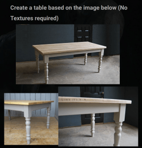
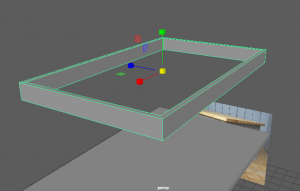
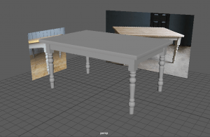
With this reference photo on the right, I split the images into multiple images, then imported them into a new Maya scene by going to View-Image plane – import image – sourceimages, and displaying them in an appropriate place.

The Images in the scene
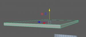
I started by placing down a cube shape for the base of the table. I added a bevelled edge that gave it a similar shape as the reference photo.
![]()
To create the under-framing of the table, I placed down two cube shapes, one bigger than the other. I used the boolean tool, difference, to create a hole in the middle of the under-frame to create an apron look to connect the top to the legs.

This was the result of using the boolean tool, I then placed this underneath the top of the table.

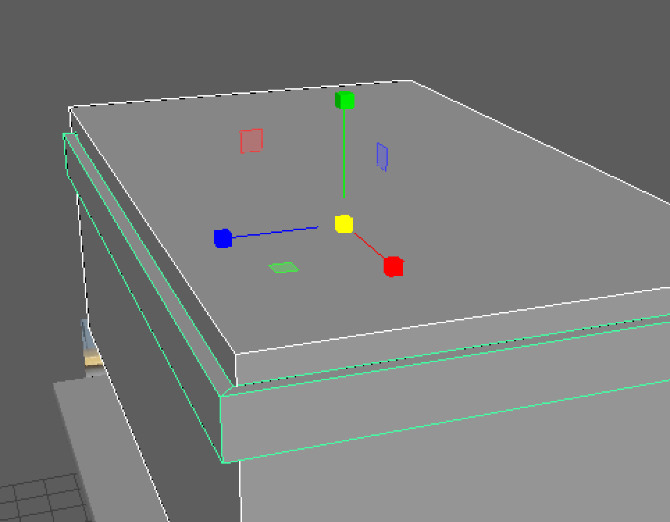
Moving on I started to work on the legs of the table. These parts are what connect the long leg to the under-framing. I placed down a cube shape and used the Multi-cut tool to create more edges and vertices. I was then able to alter the bottom vertices to make it more round as it is ![]() on the reference.
on the reference.
I copy and pasted the same shape around the four edges of the table. I made sure to try get the x,y and z axis and placement consistent and similar to each other throughout.

This is how the table looked with the top, the under-frame, and the knee of the leg joined together.

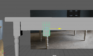
Now it was time to make the legs of the table. I started off with a cylinder shape and compared the size to the reference so I could work effectively.
I made use of the multi-cut tool to create vertices all around the cylinder. I placed them on the parts I will be scaling to match the design of the leg in the reference.
At this point I had roughly shaped out where I will be shaping the cylinder.
![]()

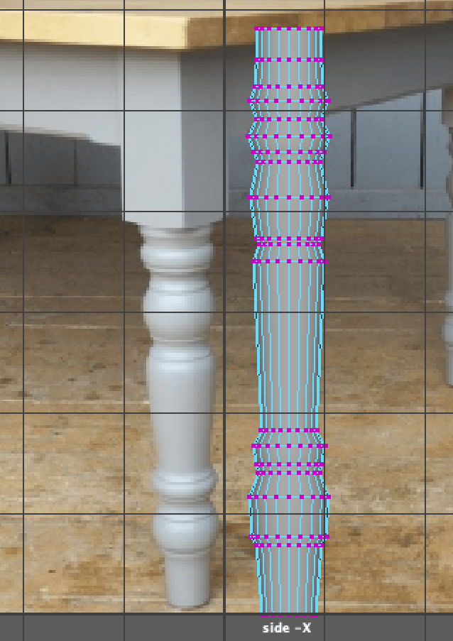
I made sure to go in and out of the different perspectives I was using to make sure I wasn’t scaling the cylinder the wrong way and making sure the shaping was looking okay.

Here is the leg with a lot more detail with the use of the multi-cut tool. During this time I had been sculpting the shape and making sure it resembles the reference. However at the angle it was at, it was quite difficult to interpret but I managed to work with it and finish off the leg.
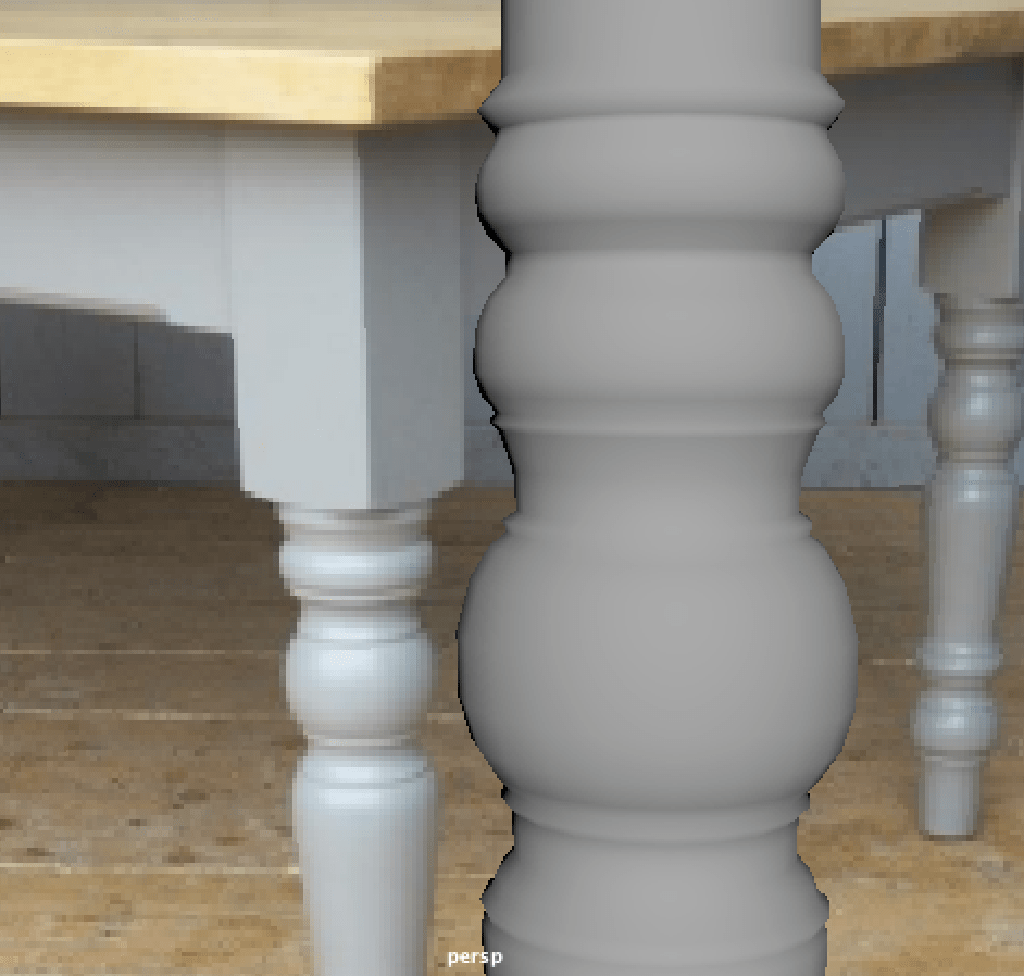
Here is part of the leg without the mesh to showcase the details. I attempted to recreate those lines around the ball shapes on the reference by making a small ring scale outwards a bit to enhance the shape more.
Here is my finished leg which, in this screenshot, I had placed the leg in similar axis and position to the knee of the leg is positioned.

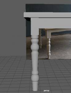
Here is where I had copy and pasted the leg each time to fill in the rest of the edges of the table. I made sure to keep track of the axis and position the legs right in the middle of the knee part to keep it correct looking.
I was using the control panel where displayed is each axis and rotation number – I used these numbers to help me position each leg together in the same place as the knee part.
To finish up, I combined each part together to make it one object, cleared the history and made sure there weren’t any more mistakes around the mesh using the cleanup tool.
I actually enjoyed making this model. It was quite simple but challenging without any guidance. The hardest part was making the legs, as it was time-consuming to shape, but other than that, I think I did a good job.

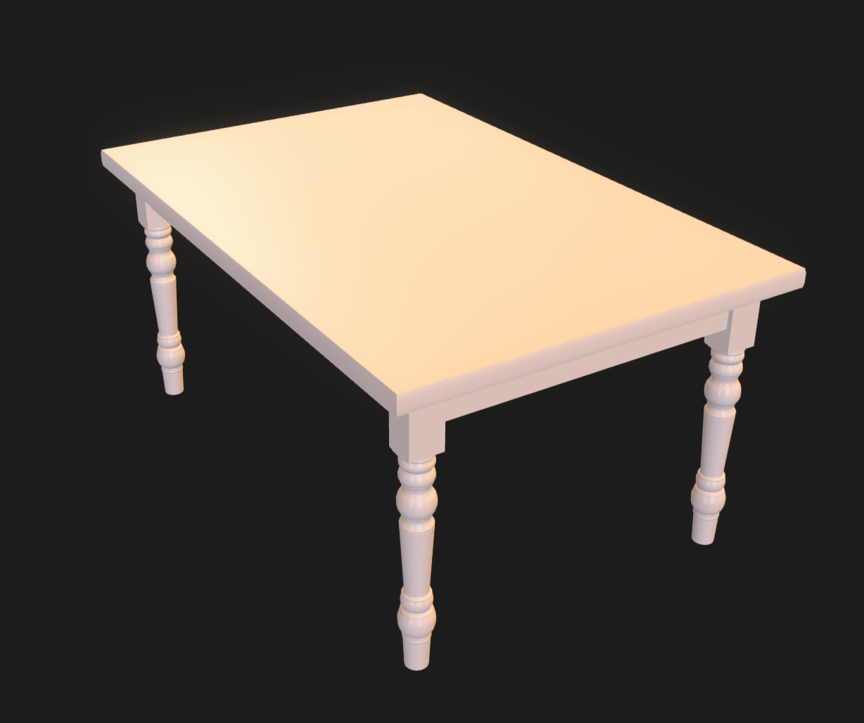
Here is the table I made that I posted onto the model viewing website, P3D.in. It gives a nicer look to the model and provides lighting and texture in the editing section.
Week 1 – Vase/Jug
This is the start of the weekly modelling challenges. To start off I am required to model a simple vase/jug object in the 3D modelling software, Maya. I will be following my tutors tutorials and tips on how to go about this task, and as I do this I will be documenting the challenges/mistakes/problems I encounter during this time.
Source: Weekly Modelling Challenges, Week 1 – Vase/Jug, Vase model Part 1-5.mp4
I started off by looking for a reference photo for a vase on the website Pixabay.com that my tutor recommended. I was looking for an image that had a simple design, and is in a good angle for me to interpret the shape.

I first picked out this jug image that included a handle and a unique-shaped sprout, but the angle it is in would have been difficult for me to attempt as my first model, so I kept looking.
I found this vase image that had an interesting cup shape and two handles. It is also placed in a good angle to work from. Though I decided to keep looking. Even though I liked this shape, I wanted to start off with something more simple. I may look back on this vase later on to try out in my own time.

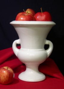
I found this vase image that I thought was perfect to start off with. It had a simple round body design and was placed in a good angle for me to work from.
 I placed my reference images onto my display by going to View-Image plane-import image and picking it out from my sourceimages folder that I saved the image into.
I placed the images into one layer, and set them to R for Reference so I don’t accidentally click on it as I work on the model.
 I placed down a cylinder as my base, and turned on vertex mode to drag the cylinder to be the same height as the source image, so I am effectively working from reference.
![]()

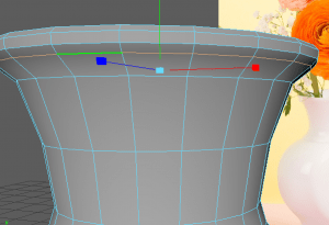
I start using the Multi-cut tool and holding the control button to add rows of vertices to give me the ability to manipulate the base into the vase shape.

Here you can see where I’m beginning to shape the object to where the main points of the vase are etc. how far it goes inwards/outwards.

the result of shaping the vase

As soon as i’ve got enough rows of vertices to create a smooth shape of the vase, I moved onto detailing the bottom of the vase. It requires a rounded, thick stand rather than a straight diagonal line.

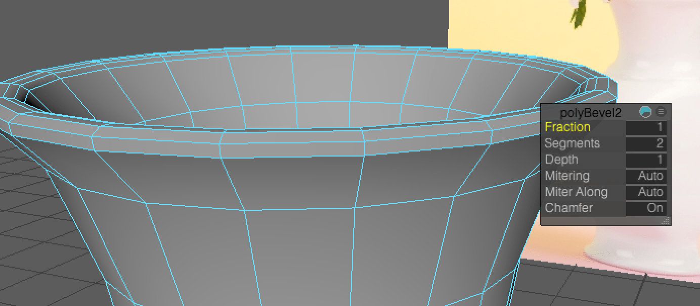
I used the bevel tool to manipulate the stand even more by adding more fractions to the area of edges I selected. This created a more fitting shape for the vase.![]()

Continuing on, we are required to replace the triangles that form on the top and bottom face of the vase, to four-sided shapes. I clicked the vertex in the middle, and used the bevel tool to stretch out the circle until it creates a multi-sided shape around the face.
![]()
![]()

However this turns into an NGON. To prevent NGONs in the mesh, I used the Multi-cut tool to draw in lines across the face that helped give each shape at least four sides.

![]()
Here I have bevelled the top face of the vase. I highlighted the vertices of the face and equipped the extrude tool to push the middle of vase downwards. This creates the hollow inside on the vase.
(I used the multi-cut tool on the top face after the extrusion)

Heres how the extrusion works when it is pushed down with the move tool.

I continued the process of extrusion by selecting it, moving downwards to each row, scale it to the direction the sides are positioned to, and press G to repeat the process. I stopped the process just above where the stand of the vase is.
After this I went onto creating a more rounded rim to the vase. I selected the edges by turning on edges mode, shift selecting one edge, then shift double-selecting the edge next to it to select the entire row of the edges. I was able to use these selected edges to bevel.
 Here I am using the bevel tool to manipulate the rim of the vase to make it stick out more and become more rounded. I added 1 fraction to the edges.
After this I gave the vase a smooth material, I cleaned up the history and looked to see if there were any mistakes in the mesh.
 This was my first attempt at modelling the vase. This was also my first time modelling in general so I think I did a pretty good job. I wanted to attempt the modelling a second time so I definitely have a good idea of what Im working with.
I did make a second attempt before I started over and did the third attempt below. I started over because I was accidentally positioning the edges of the vase after I had made the extrusion in the inside – this made it so the inside shape was inaccurate to the outside shape, which I thought would cause problems in the future.
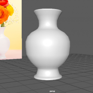
This is my third attempt. I like this one better as the body is much more like the reference – its more lifted, and the stand and rim of the vase is more rounded as it goes inwards. I added a simple PhongE material to match the design of the reference. I am not great with lighting yet, but I did add a point light to give the vase a highlight, again like the reference.
I managed to finish this model with no mistakes in the mesh of the vase.

This is my rendered image of two versions of the vase I modelled. I don’t exactly understand the process of rendering yet but this is my best attempt. I made one vase with a PhongE material set to white to resemble the reference photo I was using, then I added the Maya Marble texture to the other vase that creates a unique, blue design.
Overall this was difficult to achieve as its my first try with Maya. I came across complications when snooping around the options for rendering the scene and creating its material. A few times the application did crash on me due to a mis-click or something that couldn’t engage with my model. It is a slow learning process but it makes me more ready to tackle the next model.