This week for the weekly modelling challenges I will be modelling a table. We were given just a reference sheet to work from to challenge our knowledge and skills of Maya so far.
Source: 3D Digital Literacy, Announcements, Week 2 Modelling Challenge
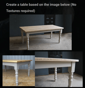
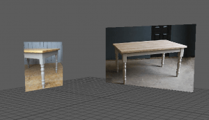
With this reference photo on the right, I split the images into multiple images, then imported them into a new Maya scene by going to View-Image plane – import image – sourceimages, and displaying them in an appropriate place.
The Images in the scene
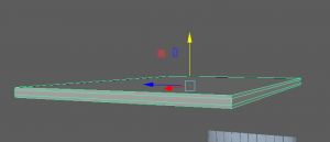
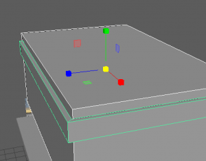
I started by placing down a cube shape for the base of the table. I added a bevelled edge that gave it a similar shape as the reference photo.
To create the under-framing of the table, I placed down two cube shapes, one bigger than the other. I used the boolean tool, difference, to create a hole in the middle of the under-frame to create an apron look to connect the top to the legs.
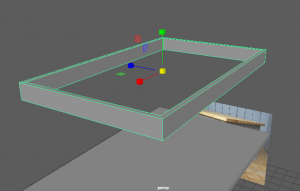
This was the result of using the boolean tool, I then placed this underneath the top of the table.
Moving on I started to work on the legs of the table. These parts are what connect the long leg to the under-framing. I placed down a cube shape and used the Multi-cut tool to create more edges and vertices. I was then able to alter the bottom vertices to make it more round as it is ![]() on the reference.
on the reference.
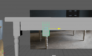
I copy and pasted the same shape around the four edges of the table. I made sure to try get the x,y and z axis and placement consistent and similar to each other throughout.

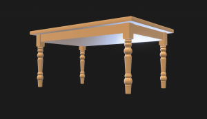
This is how the table looked with the top, the under-frame, and the knee of the leg joined together.

Now it was time to make the legs of the table. I started off with a cylinder shape and compared the size to the reference so I could work effectively.
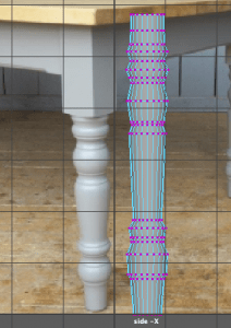
I made use of the multi-cut tool to create vertices all around the cylinder. I placed them on the parts I will be scaling to match the design of the leg in the reference.
At this point I had roughly shaped out where I will be shaping the cylinder.

I made sure to go in and out of the different perspectives I was using to make sure I wasn’t scaling the cylinder the wrong way and making sure the shaping was looking okay.
Here is the leg with a lot more detail with the use of the multi-cut tool. During this time I had been sculpting the shape and making sure it resembles the reference. However at the angle it was at, it was quite difficult to interpret but I managed to work with it and finish off the leg.
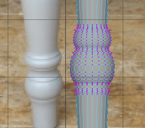
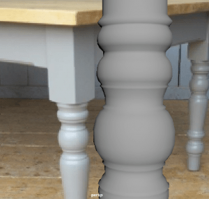
Here is part of the leg without the mesh to showcase the details. I attempted to recreate those lines around the ball shapes on the reference by making a small ring scale outwards a bit to enhance the shape more.
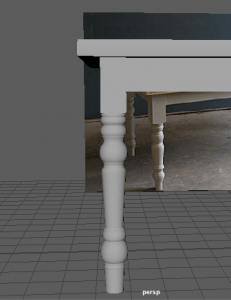
Here is my finished leg which, in this screenshot, I had placed the leg in similar axis and position to the knee of the leg is positioned.

Here is where I had copy and pasted the leg each time to fill in the rest of the edges of the table. I made sure to keep track of the axis and position the legs right in the middle of the knee part to keep it correct looking.
I was using the control panel where displayed is each axis and rotation number – I used these numbers to help me position each leg together in the same place as the knee part.
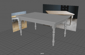
To finish up, I combined each part together to make it one object, cleared the history and made sure there weren’t any more mistakes around the mesh using the cleanup tool.
I actually enjoyed making this model. It was quite simple but challenging without any guidance. The hardest part was making the legs, as it was time-consuming to shape, but other than that, I think I did a good job.
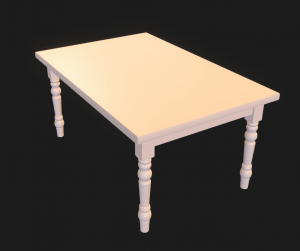
Here is the table I made that I posted onto the model viewing website, P3D.in. It gives a nicer look to the model and provides lighting and texture in the editing section.
