Week 3 – UV Mapping
This week for the weekly modelling challenges we will be looking at UV Mapping. This is a technique in 3D software where textures are mapped onto polygonal objects to make sure that they will fit as best as possible. We were required to look at multiple models to get the hang of UV Mapping different kinds of shapes and spaces to really understand how it functions.
Source: Week 03 – UV Mapping, UV intro & Dice UV Tutorial.mp4, Cylinder shape UV Tutorial.mp4, Barrel UV map Tutorial.mp4, Arm UV tutorial.mp4
First of all, we trialed UV mapping during class with a dice, a cylinder and a barrel.


This is the dice UV mapping attempt. We were instructed to place a file texture on the dice on the left and right. One dice had a structured UV and one had a cut up UV, this required us to find the faces that belong to each side of the dice.
We uploaded the file by going onto a cube’s material attribute, clicking on the folder beside colour, file, and choose this image of the dice texture.
We then opened up UV editor, placed down the image, and scaled the outline of the cube to the shape of the dice. I attempted this twice. The second time was different as the outlines were separated into faces and I had to drag them back into their dice faces.


This is the distorted cylinder UV mapping attempt. My tutor went over this in a video and I made sure I watched carefully.
I placed down the checkered texture on the UV editor scene. I highlighted the model and clicked Plantar, So the top, bottom and base of the shape would transfer onto the UV editor.
![]() The shape of the UV was quite easy to fix up. I made sure to scale it bigger and then clicked Layout, so that each part would be the same size, on the same axis, and layered out neatly.
The shape of the UV was quite easy to fix up. I made sure to scale it bigger and then clicked Layout, so that each part would be the same size, on the same axis, and layered out neatly.


This is the barrel UV mapping attempt. What I did first was select the top and bottom of the barrel, and clicked on UV on the settings bar, Planar’s settings and clicked x axis. This placed the top and bottom on the UV editor in the right way.
Then I re-highlighted the whole barrel, went onto Planar, and clicked y axis. This displayed the base that wraps around the barrel onto the UV editor.
![]() There then was stretch of the checkered texture on one side of the barrel so I went to select the edge line of this side then cut it. This then highlights the side as white.
There then was stretch of the checkered texture on one side of the barrel so I went to select the edge line of this side then cut it. This then highlights the side as white.
![]() I went to unfold the base then it is spread out onto the UV editor. I also clicked UV mode to try and scale the base UV to a straight rectangle to make it an easy shape to place a texture onto.
I went to unfold the base then it is spread out onto the UV editor. I also clicked UV mode to try and scale the base UV to a straight rectangle to make it an easy shape to place a texture onto.
![]() After these objects I went on to task myself with the next models. This included a hand/arm, a hard surface, and a man figure.
After these objects I went on to task myself with the next models. This included a hand/arm, a hard surface, and a man figure.


This is the hand/arm UV mapping attempt. This was quite difficult to handle but I followed through my tutors video to keep myself on the right track.
First I cut an edge loop on the wrist, where the hand and arm connect. This allowed me to separate the two. I then cut an edge line from the bottom of the arm to the wrist that then allowed me to unfold the arm UV.
![]()
![]()
I saw it was optional so I attempted to straighten the arm UV into a square shape but I wasn’t able to achieve it, so I moved on. I moved to the hand and went to cut an edge line between the middle of the hand, separating the top of the hand and the palm of the hand.
I tried this a couple times when something things went a little wrong etc. on the first try, I accidentally scaled part of the hand so it became distorted. The second try was just okay, I think I collected edge lines on the wrong part of the thumb but it still was able to unfold either way.


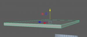
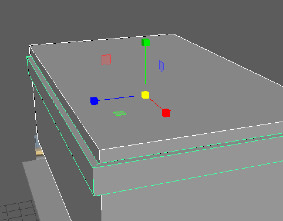
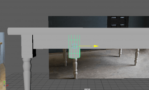
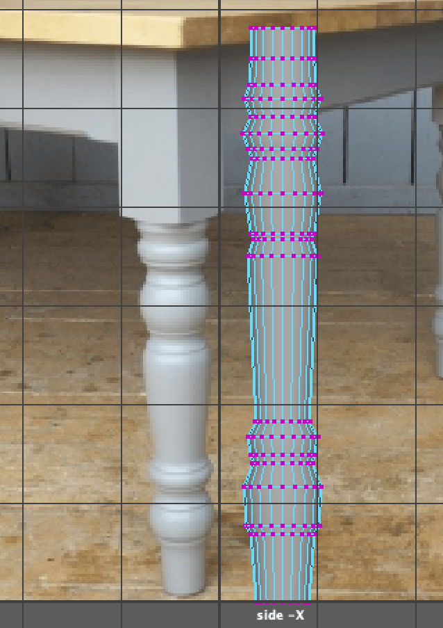
This is the Hard surface UV mapping attempt. I gave a try on this on my own and I managed to figure out a few things. First off I made sure each part of the model was UV mapped and on the UV editor, as each part was separated. I made a cut down the side of the middle tube and unfolded it to give two sides.
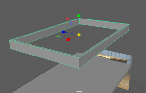
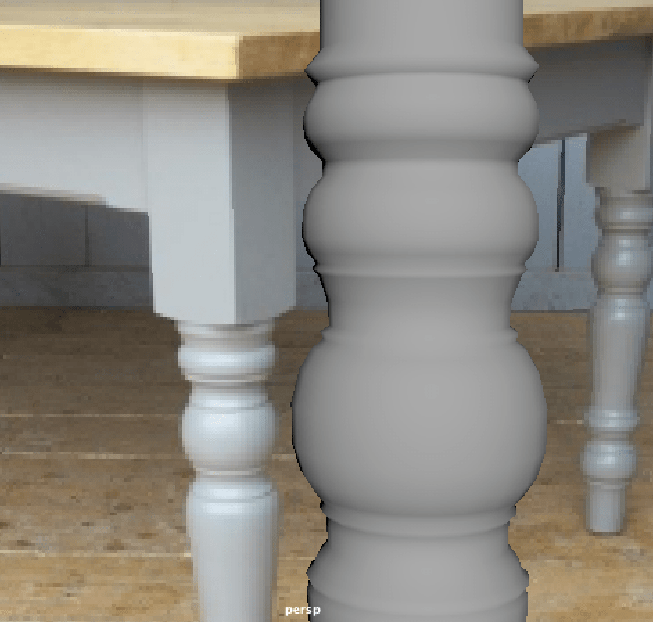
Below I attempted the two smaller tubes from the sides. As I used the Planar tool in x-axis they would display on their side, though the front faces would be stretched. i tried to select each face individually and planar these on a y-axis and eventually I got normal squares like the side view UV map.
I attempted to UV map the body model multiple times but could not find a good solution so I moved on to the next model. I was hoping to come back to this and tackle it another time.


This is the Man model UV mapping attempt. I was unsure how to go about this at first so I looked up a quick tutorial on youtube to see how someone else has attempted this and it helped alot as to where I can cut and separate each part of the body.
Source: https://youtu.be/O5Efs6TZIdQ -Autodesk Maya 2018 Quick UV Mapping and Unwrapping Tutorial


I started by turning on symmetry In my UV toolkit so each part of the body I cut translates to the other side as well. I cut by the shoulder of the arms, through the middle of the arms/hands, around the neck/ears/eyes, through the back, down the waist and in-between the legs, around the ankle and through the middle of the feet.
As soon I was done I highlighted the model and unfolded everything. They came out a little unorganised so I used the Layout option to help clean them up, and I also moved them around manually to make it a little neater.