For the assignment, I was grouped with 7 other people from both Animation and Games Design to create a game, which we called Sciophobia, which is about a reporter in the 2000’s exploring an abandoned underwater facility and the experiments that went on within.
My part within this project was to make some of the assets that went into the game, as well as texture a few of them in Substance Painter.
Final game playthrough made by Joe Burnett:
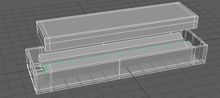
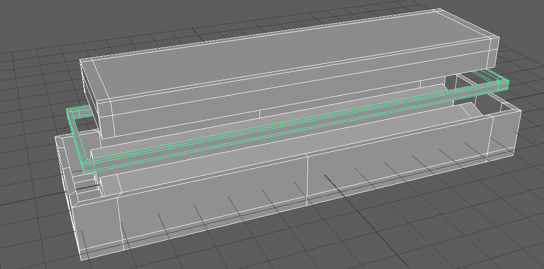
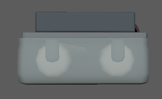
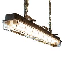
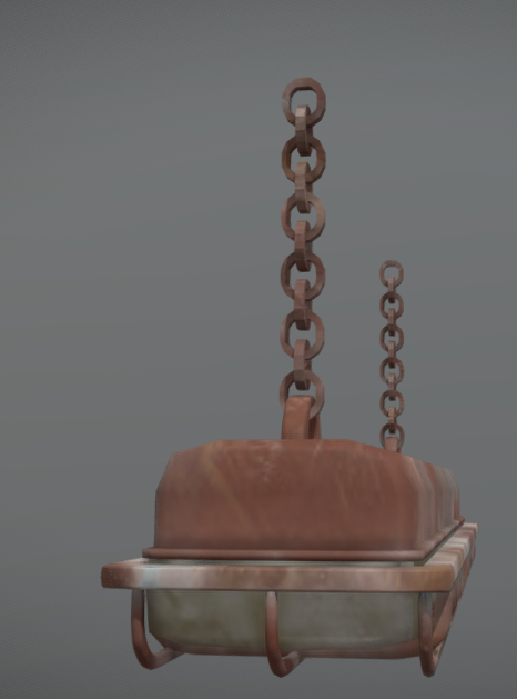
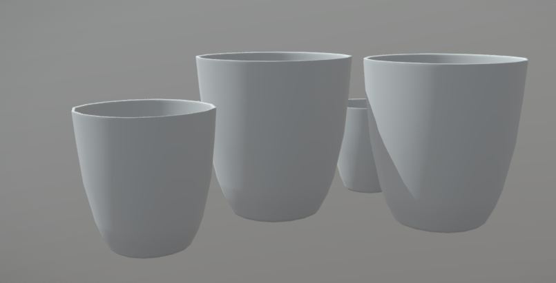
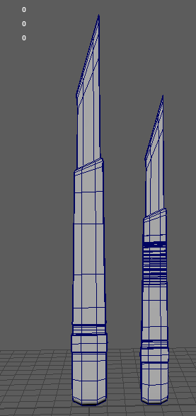
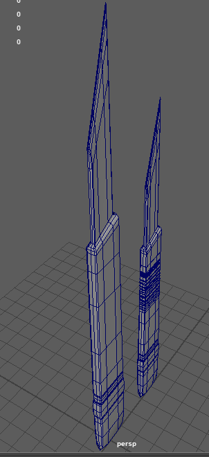
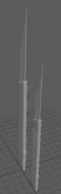
Crocodile light: modelled and textured by me
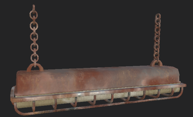
Old Soviet fluorescent light: modelled and textured by me
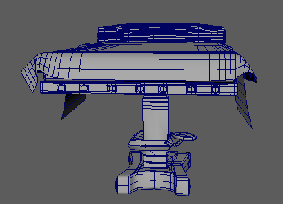
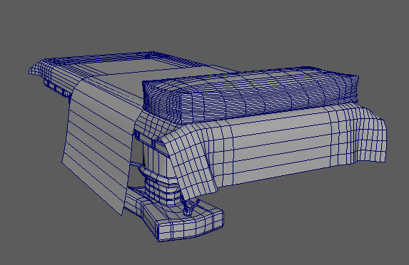
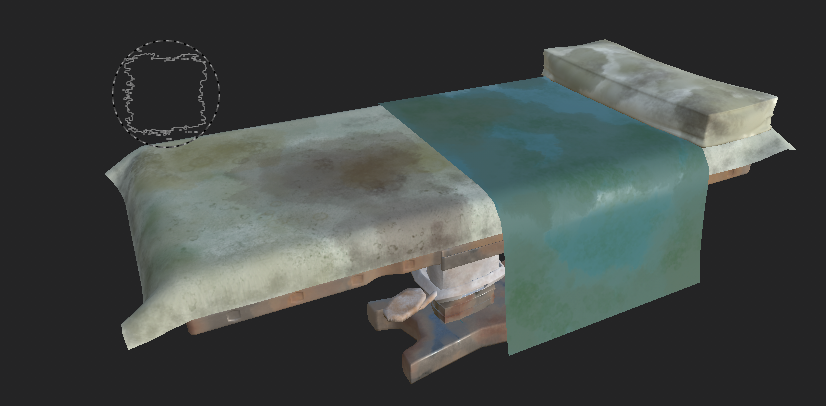
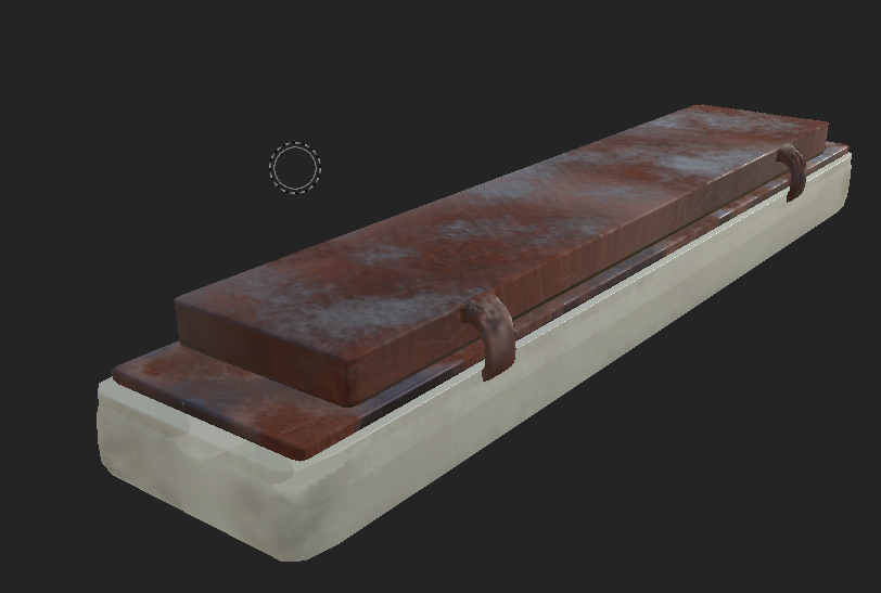
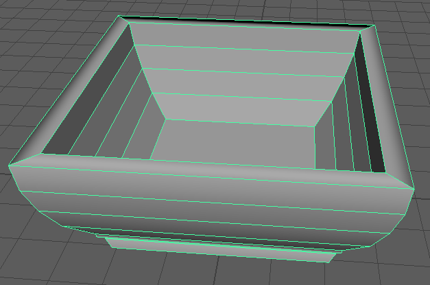
Theatre operation table modelled and textured by me
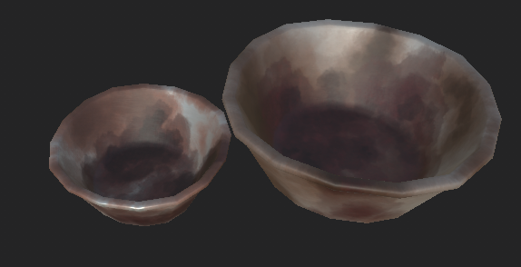
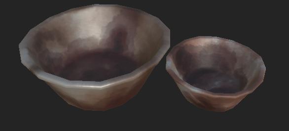
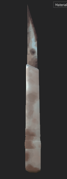
Operation dishes and scalpels by me
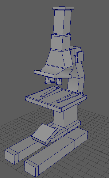
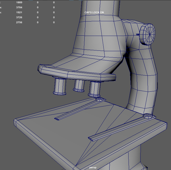
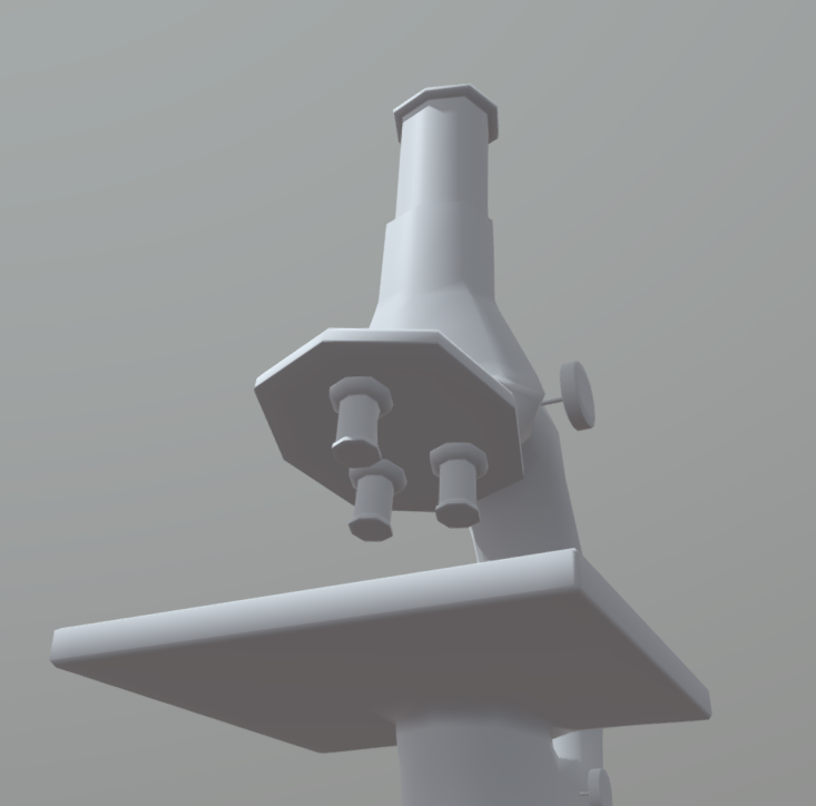
Microscope: Modelled by me, Darren textured it for the game
Blackboard with chalk and eraser: modelled by me, textured by Darren for the game
At this point, I forgot to keep track of anything ive been writing down in my note pad as everything was starting to get stressful with multiple assignments coming up so unfortunately i cant go week by week anymore.
Starting to gather reference images for the operation room, i talked to team mate Tori about who was doing what for the theatre and got in contact with Darren who offered to texture everything we’d modelled and our future models to speed up the pace of everything.
For the pillow, blanket and sheet on top of the blanket i used ncloths.
Next i worked on a scalpel which was done within 5 minutes:
I duplicated the original, scaled it down a little and gave it some ridges like in the reference above.
I did want to work on more tools but level designer Joe told me we ha more than enough models for labs and the theatre, since models from the labs could also be used here such as the crucibles, tongs, syringe, etc.
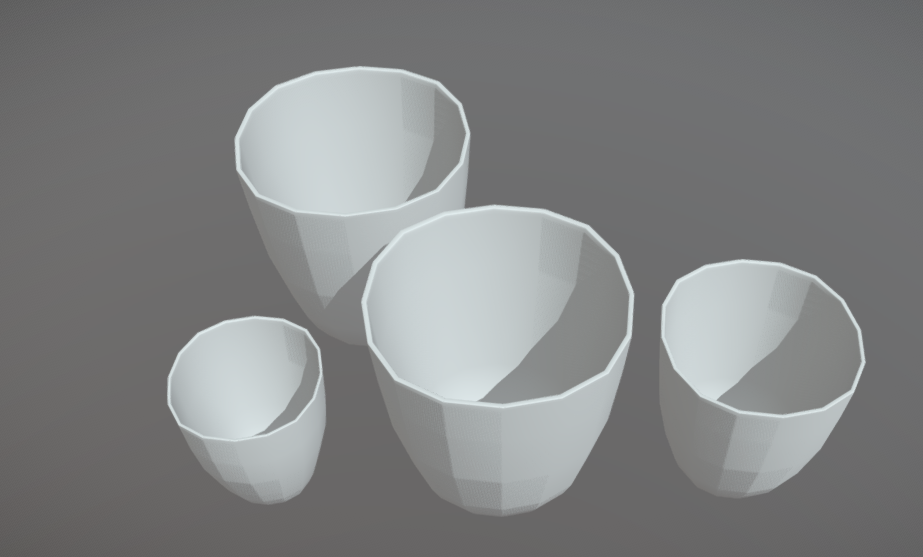
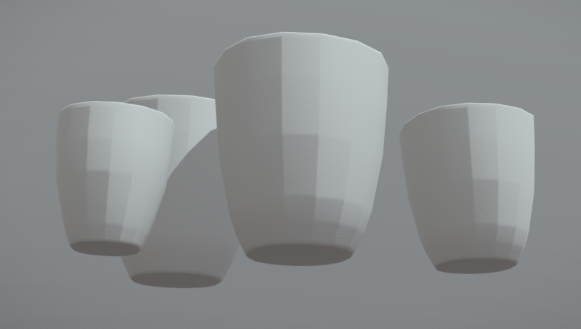
My final model was an operation dish which once again, i duplicated and scaled down for variation:
I had to texture a few of my models myself as Darren was running out of time and had a lot on his plate already, but I didn’t mind, things happen all the time in the industry so you have to expect the unexpected and be ready for anything. Luckily i was able to get my Substance account up and running again after signing up for a new student licence.
Since everything is years old and underwater, I tried to make all the metal rusted and dirty, and i put old dried blood on things in the theatre such as the dishes, scalpels and the operating table. I also tried my best to add mould and sweat stains on the tables mattress, sheet and blanket.
This week, I did some more modelling, with a total of 3 models made and then tested out the sizing of everything together in Unreal Engine 4 and how well they all looked beside one another.
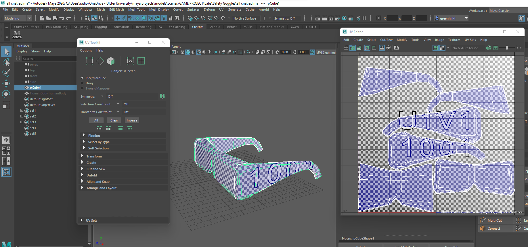
Starting off, I did some safety goggles as the scientists in the lab would obviously need to be taking precautions for their health when working. I got references of the front and 3/4 so i better understood what I was working with.
I started from a simple blockout of the shape, as you can see below, I only paid attention to one of the legs at this stage, making sure i could create an accurate shape.
Trying to copy the other side cut by cut, it looks alright from this angle but when you turn to the front you can see how off centred it was, so i decided to do the usual mirroring later on to get everything symmetrical to keep it realistic and good enough to display.
After deleting one half and mirroring it, I smoothed the whole model but it was looking a bit chunky and had far too many edges all around, so i had to clean it up a little.
Below is the model cleaned up and flattened where need be, as when you look at the references, it isn’t all rounded and there are parts that curve into others, so i wanted to capture that at this stage.
Once i was finished, i used the clean up tool again creating the awful triangle geometry you see below, but again, i didn’t know this was bad until around week 5/6. Regardless, i was happy with the overall shape and design of this model and ready to move on to the next.
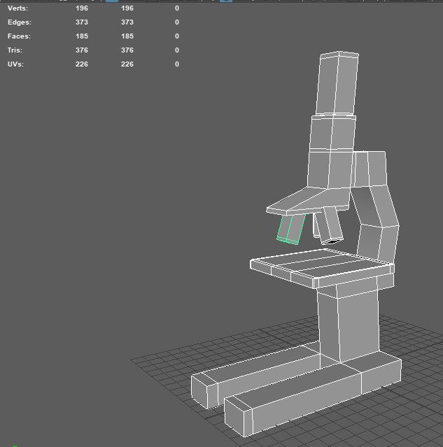
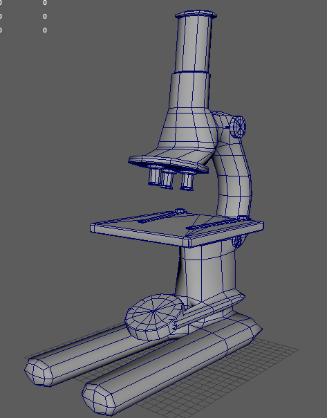
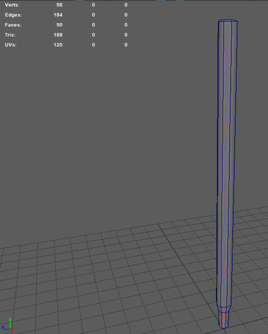
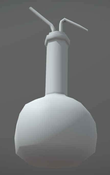
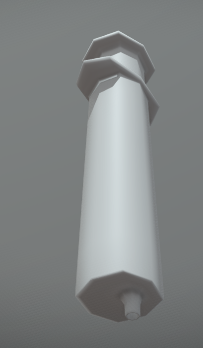
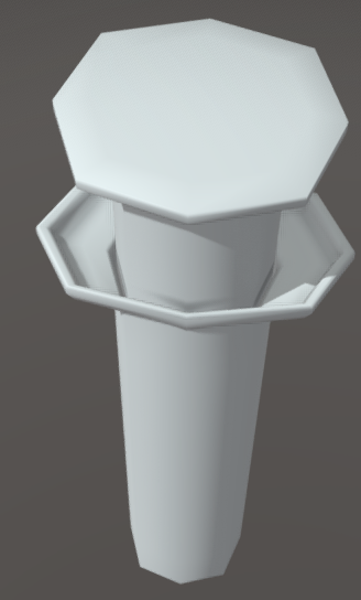
To go along with the goggles, I made a microscope as the scientists would have needed something to examine all the molecules etc going into their formulas. I gathered some references of some pretty interesting microscopes from the 60s and started modelling.
unfortunately this photo wasn’t great resolution but it did the job.
I started out by blocking in the shapes of the main body with the legs, neck and the head that’d hold the scopes.
Next i added the platform where the glass slide goes and blocked out the scopes on the head. I also tuned the legs and body so they were thinner and more accurate to the reference.
Fixing the width of everything a bit more, i then added multi-cuts where i needed the object to hold its shape after being smoothed such as the scopes, neck, leg ends, glass slide platform, etc.
Looking at the reference, i noticed there were little knobs on the sides that were used to adjust different things on the microscope, so i made on of those next which i later duplicated for the other side and duplicated it again two more times for the two smaller ones lower down.
Here you can slightly see that smaller knob lower down as previously mentioned, but i also made the slide clips that’d hold the glass slide for the scientists to keep it steady and study whats on it. I also made one of the scopes more detailed, giving it a rim and the chunky connector bit at the top that’d attach it to the head of the microscope. I also changed the scope head so it was a on a slight angle.
I extruded two little limbs from the main body that’d hold the circular glass and provided a close up of the glass slide platform.
Here i blocked out the circular glass with a cube and extended the arms that were holding it.
At this point i decided the legs need to be slightly longer so pulled the vertexes out on the z axis.
I added more multi-cuts to the neck and pulled them out with the translate tool so it looked more rounded and would smooth out more accurately.
Once happy, i smoothed everything and reduced the poly count as low as possible, though unfortunately yet again, i used the cleanup tool and it made messy geometry. There were a total of 43 iteration saves on this model, so to save time I’m going to throw in a few close ups of the finished thing and the smoothed model before it was cleaned up.
This is the smoothed model before cleanup.
The following images are the final smoothed and cleaned model.
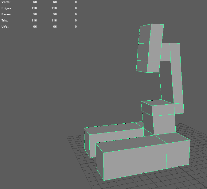
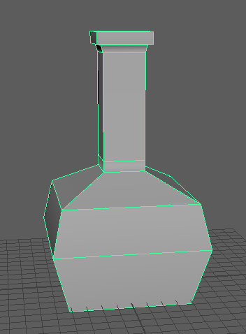
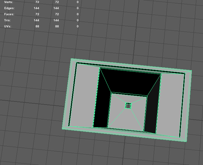
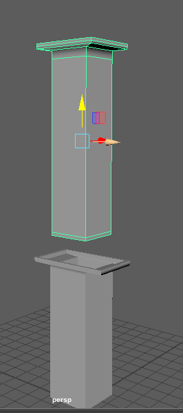
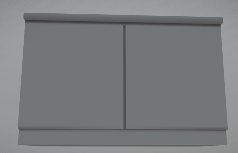
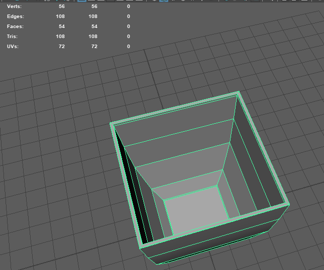
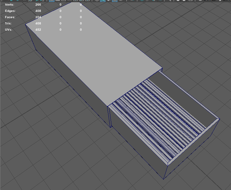
Lastly, we needed something for all the lab equipment to sit on, so i made a desk in the likeness of the school science labs desks with the cupboards on the front. I had to make 4 different variations as we needed one that would be in the middle, a left end, a right end and one with no ends.
Starting with my favourite shape, the cube, I added multi-cuts and used the scale tool on the top faces to create the bench top.
Adding more multi-cuts, i then created a dip down at the bottom and a little indent for where the two cupboard doors would meet.
This is the model with the left hang.
This one has no hang.
This one has a right hang.
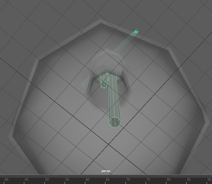
After all these models, i took them into unreal engine and tested them for size comparison an how well they showed up in the game engine.
Starting off, it was getting a little bit of a joke as the group had constantly been going back and forth between my lights, telling me one was better suited than the other then changing their minds, so I’ve honestly no idea which one if either are going to get used, and it was slightly annoying I won’t lie, but I dealt with it. I understand that being part of a development team is the ability to alter or change something completely and that not everything you produce will be used.
Moving on, this week we actually started giving out proper tasks for things to model, I was given a choice so I chose labs, as it seems quite interesting with all the different apparatus laying about and the creepy atmosphere they usually make. The team made a section on the Miro Board for all the assets we were going to need, giving me a small list of items which I just added on to whenever I thought of things.
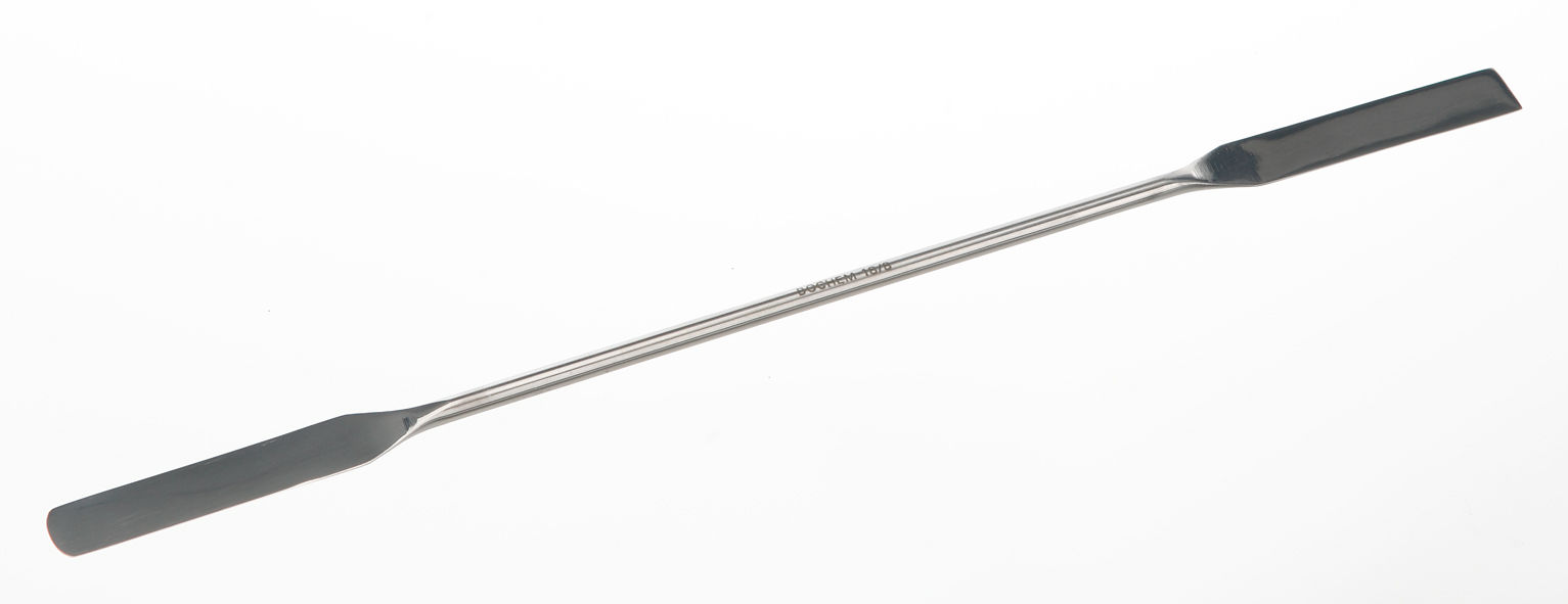
This week, I started on the models for the labs, starting with a laboratory spatula and a test tube. Before jumping into Maya though, i had to do some research on what equipment was used and stored in a laboratory, gather adequate references of different angles if possible of said equipment and create a list i can check off whenever I’ve finished modelling one of the objects.
For research, I went onto Google Chrome and typed in “laboratory equipment” and a load of images popped up, from which i took art of all the equipment and their names in one photo as this would make it easier to see what I’m working with and give me an idea of what else i could add.
Picking the spatula, I looked for references of how big it was compared to a human hand, as seen below, the shapes of each end and the thickness of the whole thing. Since its quite a small and simple piece of apparatus, I didn’t have to get too many references to know how to model it.
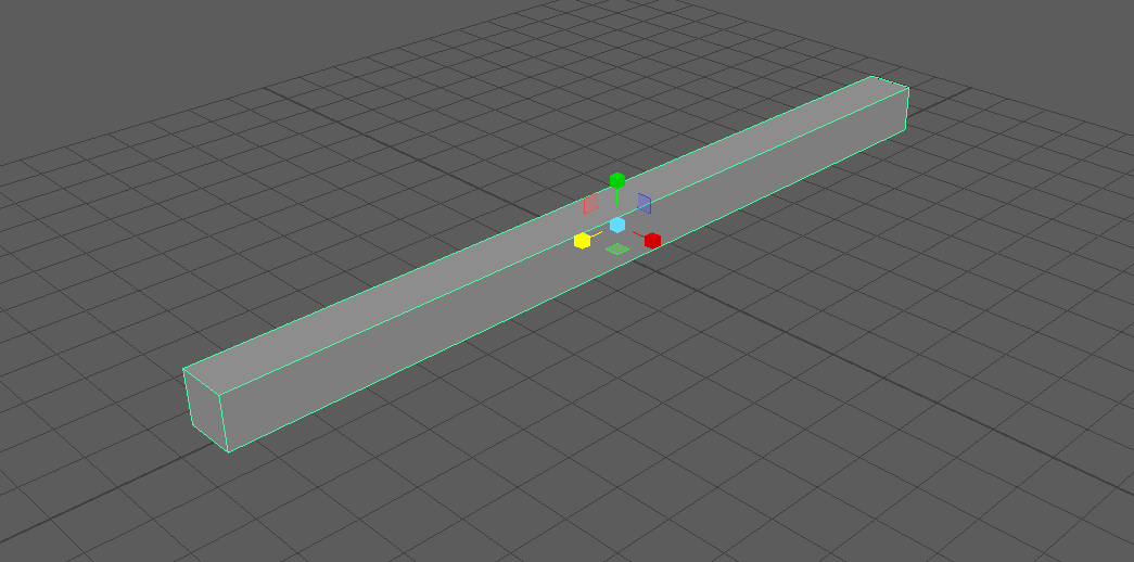
Going on to model the spatula, I started off with a cube and used the scale tool to elongate it to make a cuboid, then scaling it down on the x and y axis to make the body thinner without reducing the length i just added.
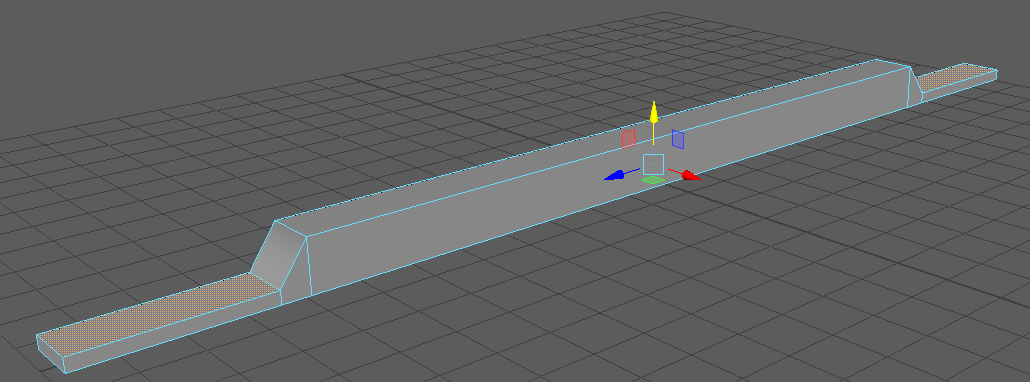
Using the multi-cut tool, i held down CTRL on my keyboard to create a loop cut and cut both ends of the shape, this would be the starting placement for the scooping edges of the spatula. I then selected the end faces on both sides and used the short cut CTRL+e to extrude them on the z axis, then selecting the top faces and using the translate tool to push them down on the y axis, giving them a more flattened appearance like in the reference.
At this stage, now almost done the model, I added multi-cuts to the places where I wanted the model to retain its shape when smoothed such as the ends of the scoops and the dip of the main body. This would also give me the nice slope down transition to the scoop that I wanted. The model was looking a bit strange and I noticed it was lacking appropriate length on both scoops and the width needed to differ from the main body, so i used the scale tool again and selected the vertexes, scaling them on the x and z axis.
Now my model is ready to smooth, so i head over to the tabs up top and under Mesh I locate the Smooth option which then makes my model more rounded, filling in more polygons to create a softer and more appealing shape. While this does look nice, I need to clean up the unnecessary edges so I can reduce what is known as a poly count which is the amount of polygons in your model that determine how high quality or low quality your finished result will look. Usually when making models, I’d try to get them as good looking and quality as possible, but since this is an asset for a game, I need to keep an eye on my poly count as the bigger the amount, the more stress the engine is put under. I won’t lie, I’d never done this before, so i was a bit confused at the start, not understanding how many polygons were too many or too little and had to consult my group and the internet for a bit of help but i understood soon enough, though it was a bit tricky to get used to remembering to keep looking over at the faces display.
After cleaning up the edges and using the Clean-up tool to make sure my model was created properly and there were no N-gons, the model is complete. This isn’t the end though, as i still have to create UVs and unwrap them so the texture will sit properly on my model.
Note: if the model above doesn’t look quite like my end result, it’s because i forgot to take screenshots of most if not ALL of my working on my models, and decided I’d remake them so i could guide you through my process. Lesson learned for next time.
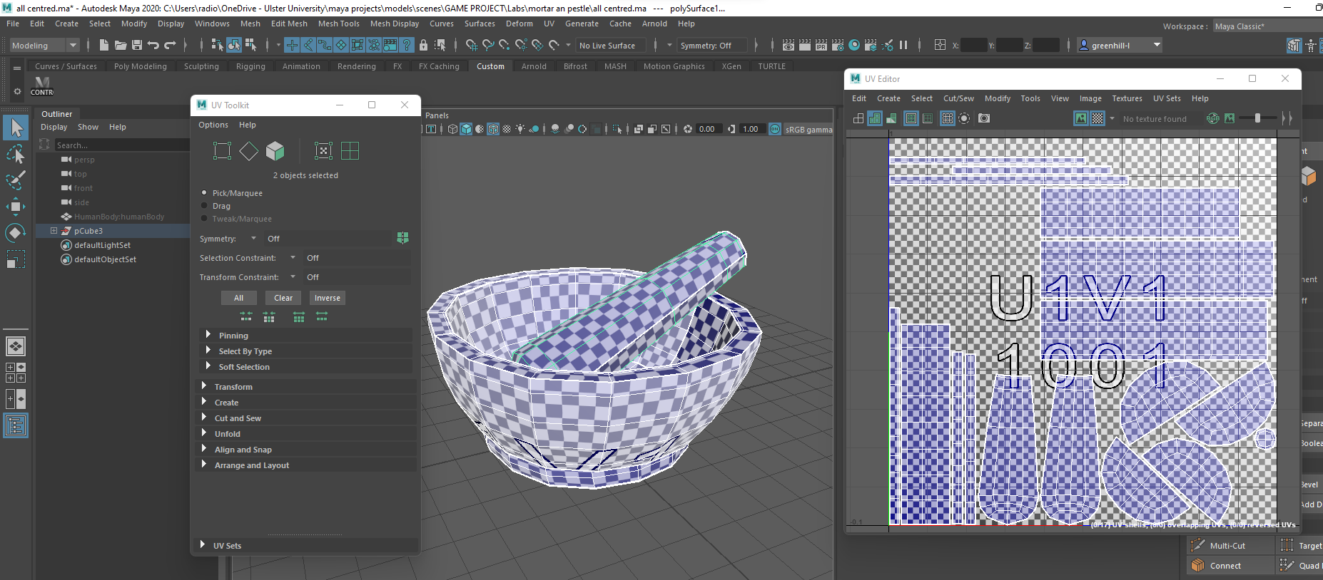
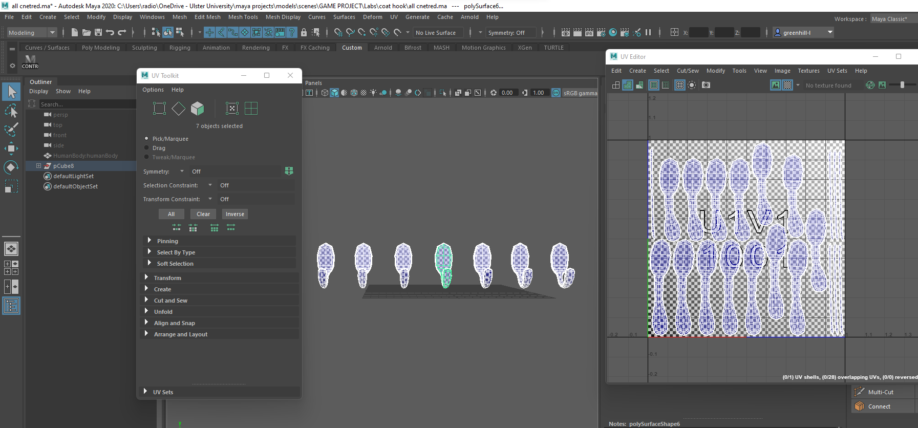
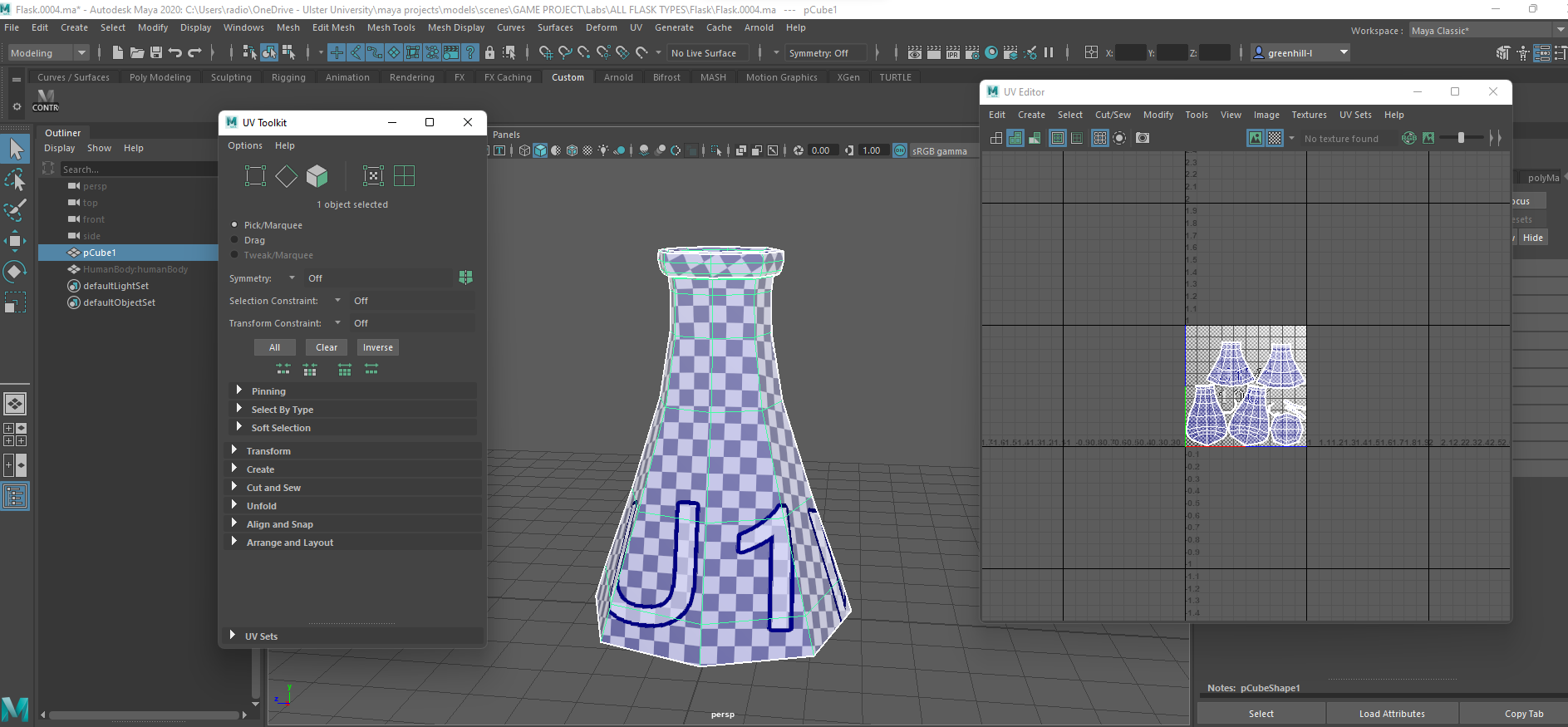
In order to UV unwrap the model, i opened the UV editor and used the toolkit for faster workflow. Selecting the spatula in object mode, i used UV shell mode in the editor and highlighted all of the shells, pressing Automatic on the toolkit the selecting all the UVs and stitching them together. My next step was to select all the edges I thought needed a cut in order to make the texture flow naturally on the model, as if you don’t cut your UVs properly, you can end up with some odd looking distortions in your textures. This model was quite simple, I cut seams at the bottom edges so they wouldn’t be seen when it was textured and placed in the game.
Below is the finished model without texture.
My next model was a test tube, so same again I looked for references of the shape and size compared to hands and other apparatus to scale my model properly and make it more realistic.
With sufficient references, I headed over to Maya to start modelling my test tube, starting out with a cube which i elongated with the scale tool on the y axis for the body length then used the multi-cut tool to cut a loop in the top where the lip would be formed, selecting the top face and bevelling it on 0.2 then extruding the face downwards to create the inside of the tube.
Adding a few more multi-cuts to the bottom and top for the structure of the tube, i selected the top faces where i wanted the lip to be and scaled them out on all axis to create the shape you see below. To make a smooth surface on the edge of the lip, i used the multi-cut tool and the middle click button on my mouse to place a loop cut directly in the middle on the top faces.
Finally, I smoothed the model two times so it wasn’t so cubic and ugly, giving me the rounded and more appealing shape you see below in the first picture. Same as last time though, this isn’t the finished model as i still have to clean it up and reduce the polygons so its not as tasking for the game to run. I do this by selecting the horizontal loops that I can delete without affecting the shape of the model on the inside and out, and delete them with CTRL+DEL so it removes the history of their cuts as well and won’t affect the model.
With my second model complete, I open the UV editor once again and get to work unwrapping the model. I start with highlighting all the UV shells in the editor and using Automatic to create the shells then select all their UVs and stitch them together and start picking the edges where I’d like to place cuts. Once I’d placed my cuts, i highlighted the UV shells again, unfolded them then hit layout to fit them all neatly into the tile set and used the rotate tool to rotate the shells the right way around then hit layout again and that was me finished.
Below is the finished model without textures, and a lambert material applied with a low transparency to create the feel of glass for showcase purposes.
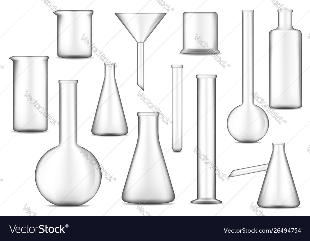
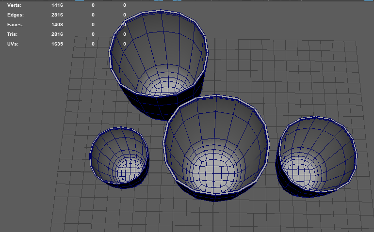
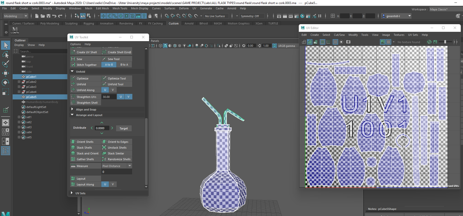
Next, I decided to work on a set of glass flasks, as these are a pretty important part of a laboratory. Following the usual routine, now ive chosen what i wanted to model, i went to google to find some references of size comparisons and the shape of the object.
Lab glass vector design of chemical laboratory test tubes, flasks and beakers. Glassware equipment 3d illustration of chemistry, biology, medicine and pharmacy research technology, scientist tools
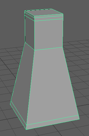
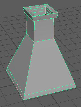
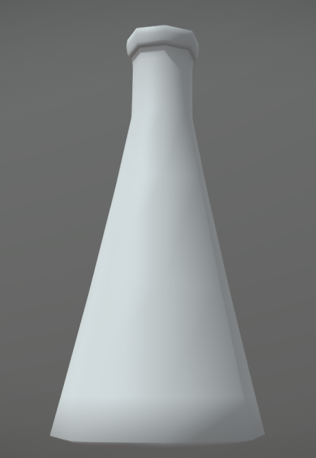
For the first flask, I chose one of the simpler shapes of the triangular spouted flask. To start with, I stared yet again with a cube and used the scale tool to scale it up on all axis to make the general model bigger, then again in the y axis to give it the tall body, followed by a few multi-cuts near the top to start the spout and one on the bottom to help form the shape of the flask.
To fix the shape, i scaled the bottom two edge loops out on all axis and moved the spout down a little so it looked more short and stout rather than thin and tall. To make it look more like a flask, I had to give it an inside and a rim which I did by selecting the top face of the spout, bevelling it and then extruding the face down into the spout where i then did another extrusion, using the wireframe and sideview to scale it out and place it appropriately near the bottom of the flask. To create the rim i then selected the faces on the outside of the top of the model and scaled them out a little on all axis, moving the edge loops with the translator tool so it could support the shape.
I smoothed my model and cleaned up any edges that were unneeded so I had a simple clean shape of flask. I gave it a lambert material and turned down the opacity so it looked more like glass as seen below.
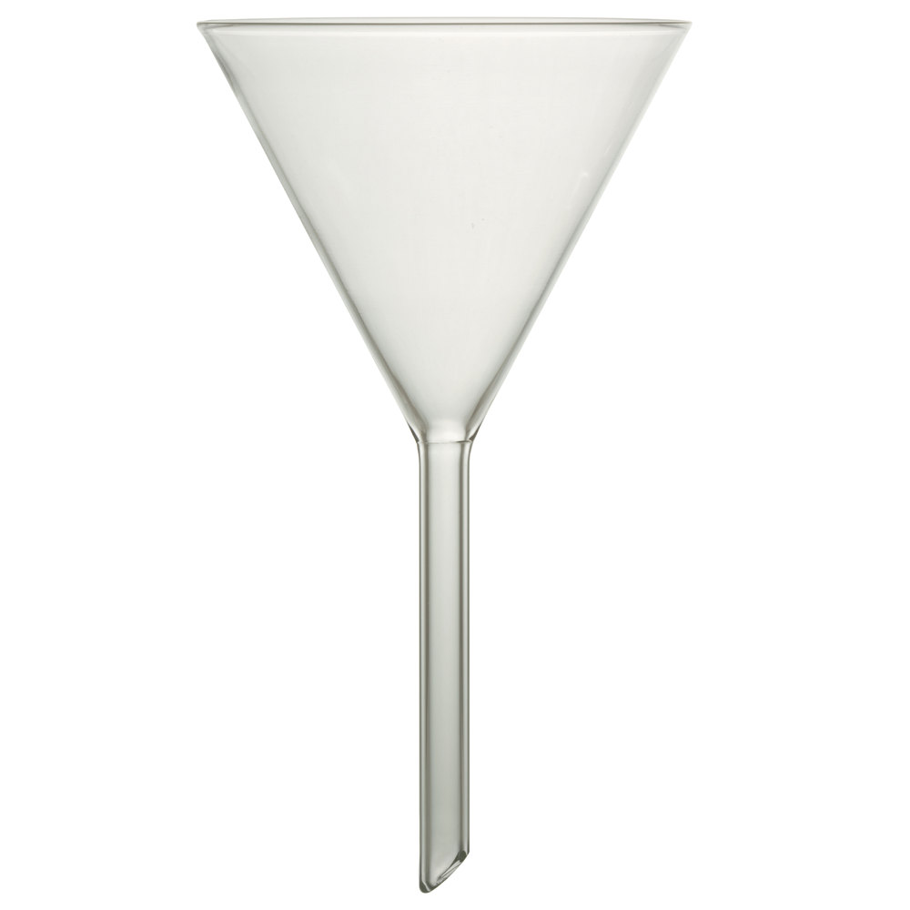
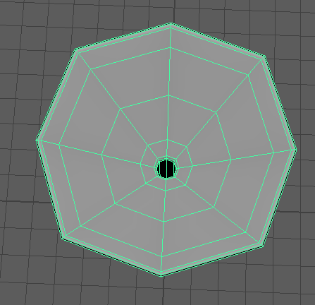
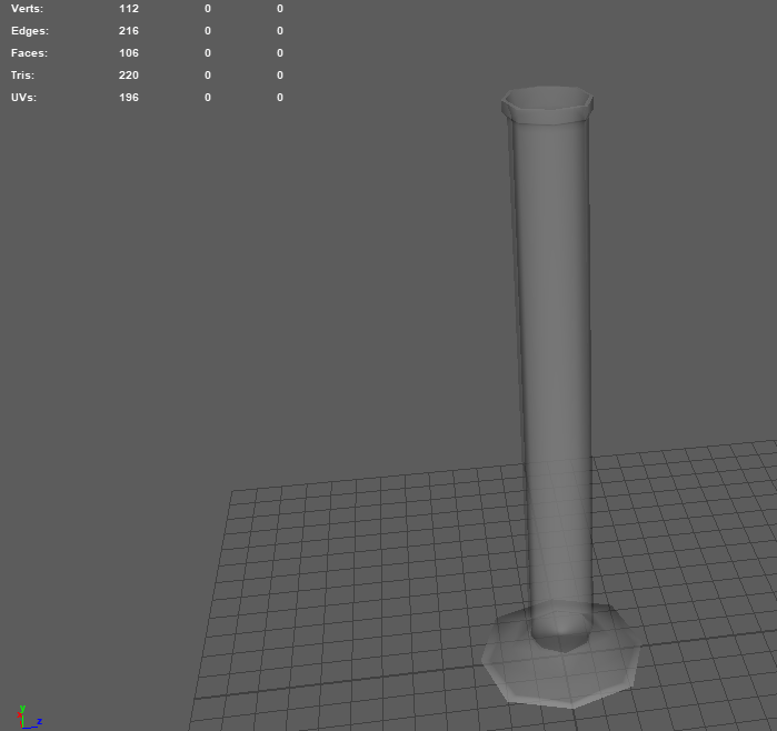
Once I finished my first model, I started on the funnel which i didn’t feel the need for a reference as its so simple, but better safe than sorry, so i headed back to google.
Starting with a cube, I elongated it and selected the top face, extruding it, placing a multi-cut and then scaled the top of that extrusion to create the big funnel shape. I placed a few more multi-cuts so the whole thing held its shape whenever smoothed. I checked this out quickly by previewing the smooth with 3 on my keyboard and from there decided where i needed to place more cuts.
To create the hole throughout the object, I selected the top face and gave it a bevel, then extruded it down into the funnel shape, going into side wireframe view and extruding it again all the way down the tube of the funnel where i then deleted the bottom face and bridged the edges of the extrusion and outside of the tube so it created a rim as seen in the bottom photo.
With my model basically already complete, all that was left was to smooth it and clean up the unnecessary polygons with CTRL+DEL, delete all history and freeze transforms so that when it was time to UV unwrap, it wouldn’t distort or do anything weird.
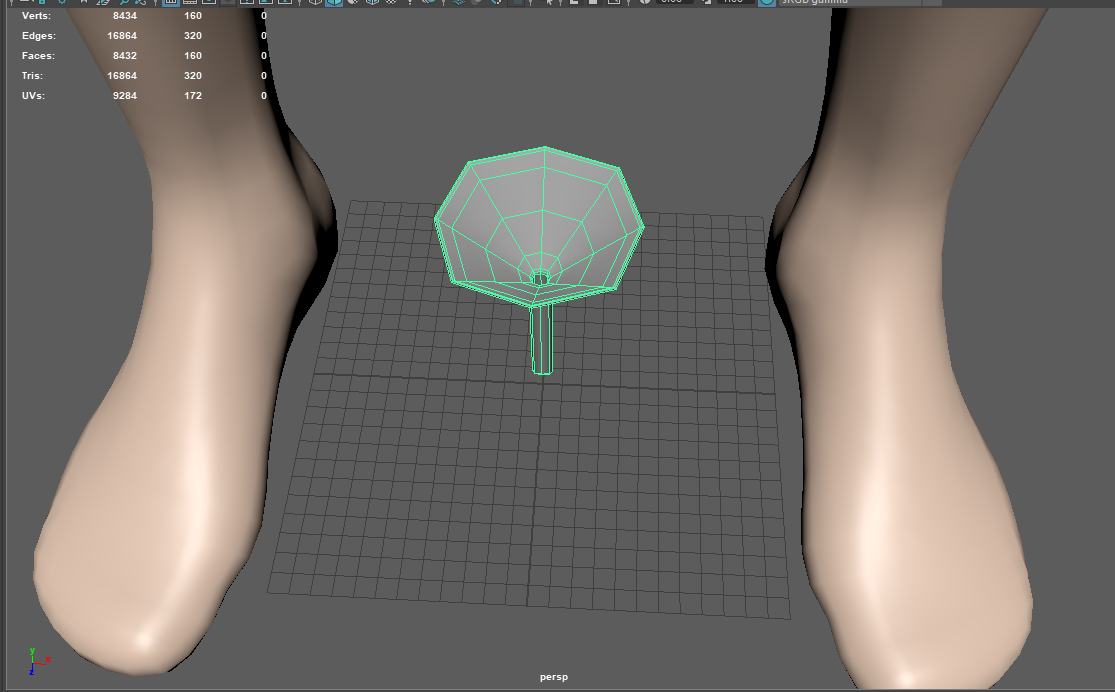
I then imported a human model from the content browser and compared the size of the funnel to the rough sizes of the hands and feet, then deleted the human when finished as it was no longer needed.
With the funnel finished, i moved on to a second flask which was honestly just a duplicate of the first flask with some size change and a few edge loops moved around, as there are some similar flasks in real life science labs just differently sized or some parts are slightly different such as in this model, the spout is slightly longer and the whole thing is taller and thinner.
I also made and UV unwrapped a cork for this model as seen below.
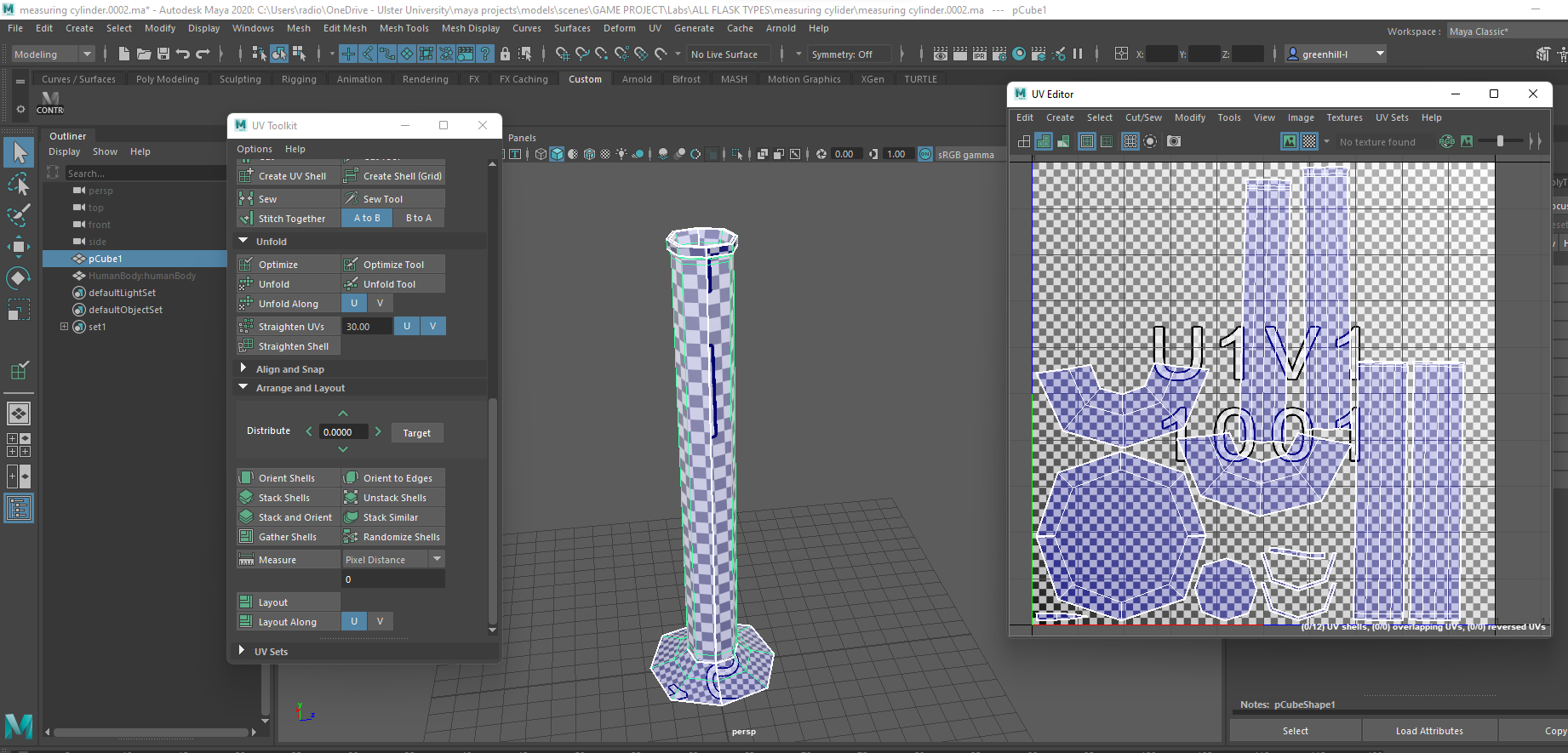
Next i looked up references for a measuring cylinder as that shape was a little bit more complicated and quite hard to do from mind alone.
3 empty measuring cylinders made of glass in white back
I’ll admit i didn’t notice the tiny spout the second one has because i thought it was just flat, which is why my model has no spout, but from real life experience i know this apparatus can vary greatly in height and width, so I wasn’t too limited in how big or small i made this model.
As usual, i used a cube and scaled it up on the y axis to get the tall tube, put a few multi-cuts on the top where the rim was going to form, selected, bevelled and extruded the top face down into the tube to create the inside of the cylinder. I then selected the bottom face and extruded it, scaling the bottom vertexes out on all axis to create the disc shape, placing a few more multi-cuts. Creating the rim, i selected the outside ring of faces at the top of the neck and scaled them out on all axis, moving the edge loops below up a little to create a better structure for the rim.
Once finished with the modelling, I smoothed it and cleaned up all the unneeded edges, deleted all history and froze the transforms. I also added a lambert material on to the model and turned down the opacity to create a glass look again. As a precaution, I used the Cleanup tool to check for any n-gons and found there were none so I claimed this as done and moved on to the next.
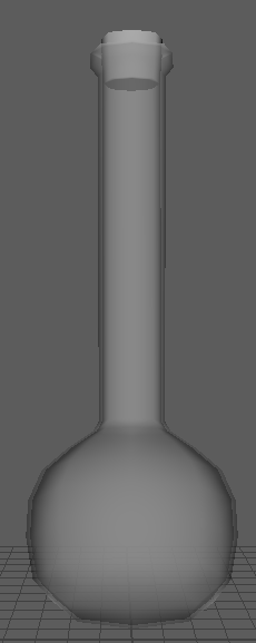
My next models were two spherical flasks, which was something i wasn’t too used to making yet as the only other spherical thing id made similar to this was the vase homework back in first year. Nevertheless, I used the images at the top of this blog for my references and got to work.
I’m sure you’re sick of hearing it by now, but, I started with a cube and scaled it up on all axis, using my middle mouse button to create a multi-cut in the dead centre, selected this new edge loop and scaled it out on all axis to create the puffed up look which would later become a round sphere. For the neck, I selected the top face and extruded it upwards, placing multi-cuts at the bottom to keep the shape together without altering the bottom of the flask, and at the top to create the rim for later. The neck at this point though still needed fixed so i scaled the vertexes down on all axis to create the slim neck you see in the above image.
To create the rim, i followed the same procedure as the last few flasks and selected the faces on the outside of the top of the neck, scaling them out on all axis and moving the edge loops further up to support the shape. I still need to create the inside of the flask, so you know how it goes, select the top face, bevel it then extrude it down with extra extrusions due to the spherical shape. I also had to add a few extra multi-cuts to the bottom using my middle mouse button, as i needed more edges to work with so i could scale them out to create a rounder shape before smoothing.
I smoothed my model and cleaned it up as seen above, but I now need to make the bottom flat so it can actually sit up and not fall over. I honestly didn’t even notice this myself, it was a group member, Darren, who pointed it out to me, so thanks!
Now my model has been flattened, I also made it a cork like in the reference image as it made it more interesting and gave it a chance for some variation when in game, as i made them two separate objects. The pipes have holes in the top and bottom as seen in the following images, which were made similarly to how i made the funnel.
My next flask I created pretty much like the last, though i made it smaller, taller and thinner and gave it a different cork for more variation.
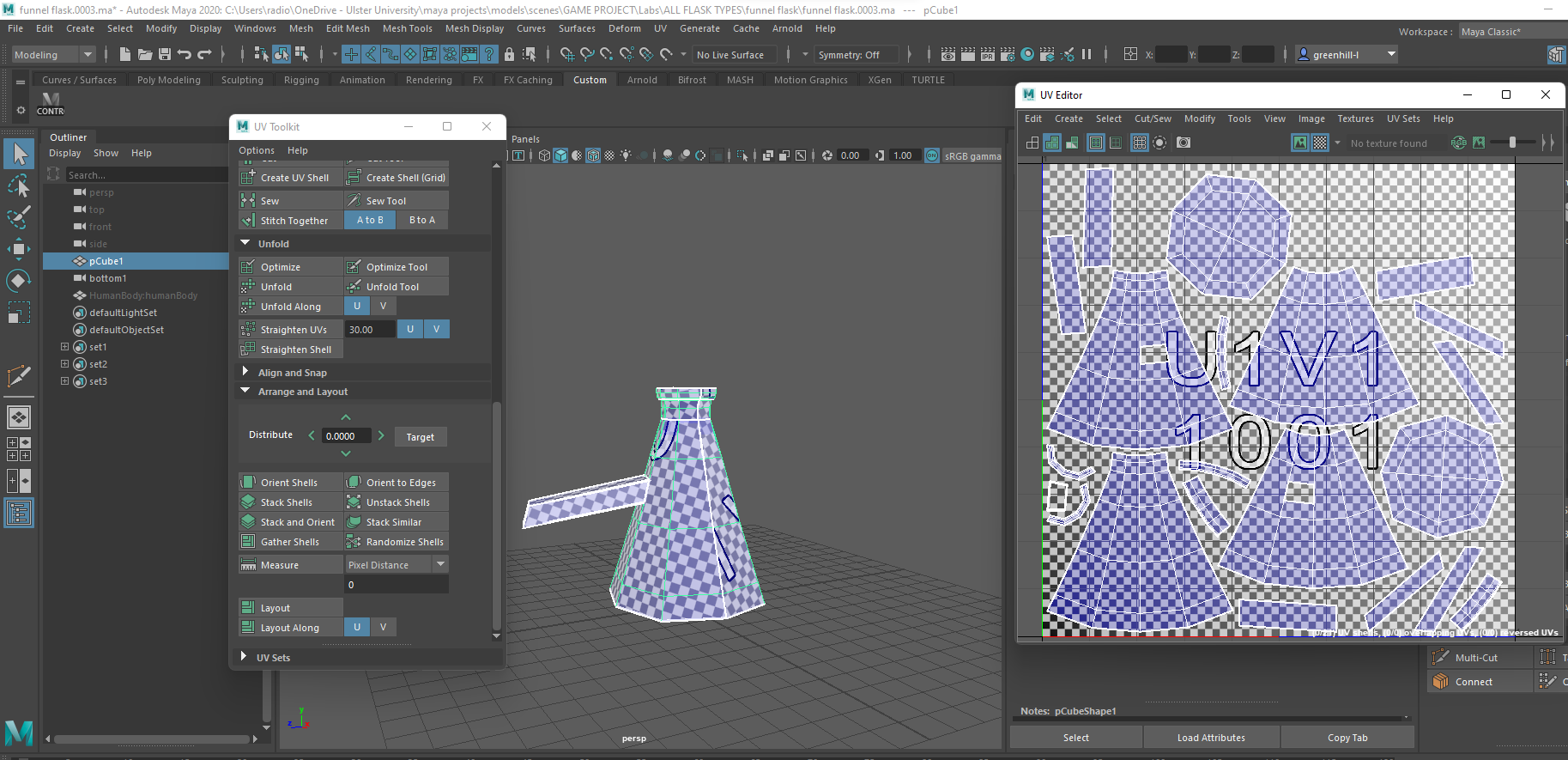
My final flask to make was the funnel flask which was a bit tricky with the little spout coming out the side. I couldn’t find any references for this as i couldn’t find out the name, so i just used the image in the first flask references as my guide.
This flask was made the same as the previous ones, using the funnel method to give the spout its hole and rim.
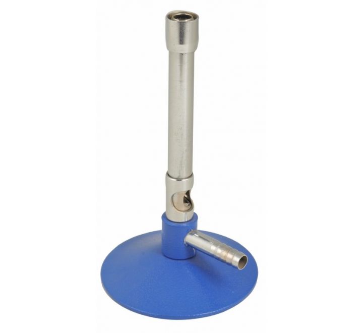
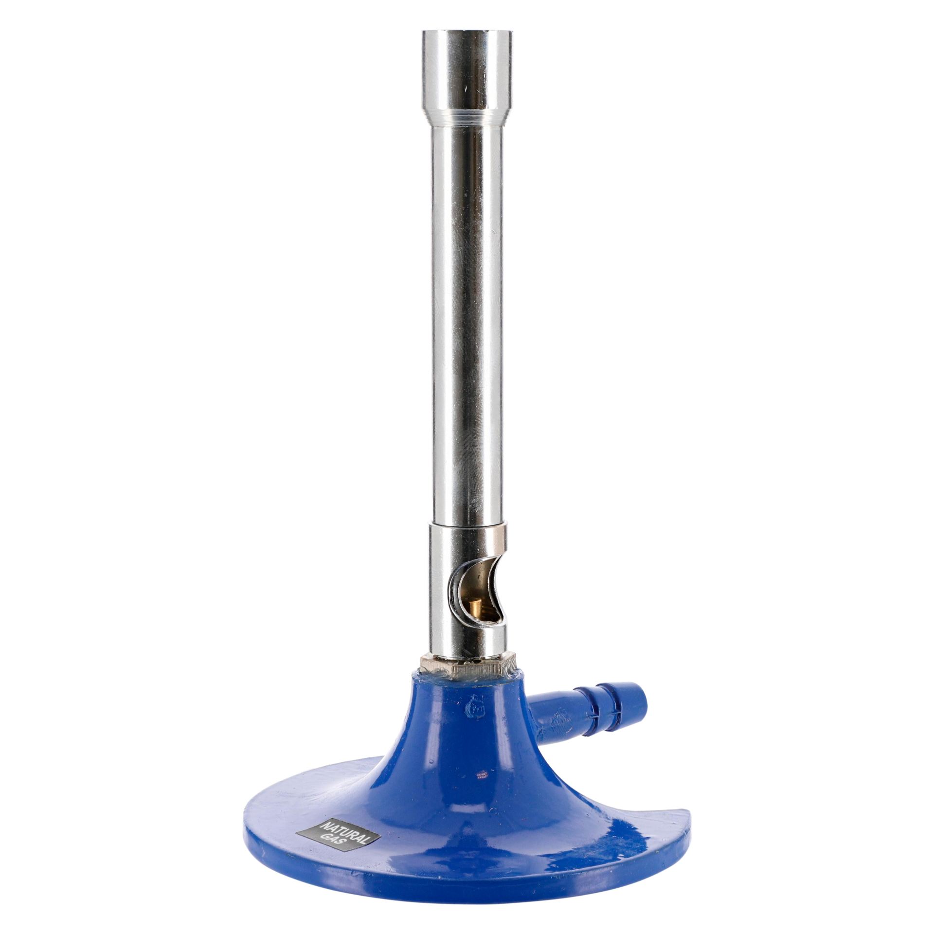
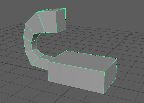
Finally moving on from the flasks, I wanted to make a bunsen burner, so i gathered some references before starting, though after making all those flasks I found they gave me a good amount of knowledge in how to create most of the other assets i needed.
I went for a Bunsen with no hole in the base as i thought that’d be a bit too complicated and didn’t want to waste time and since these are just small room detail models, it wouldn’t matter much anyways and would give me more time for other models.
To create the Bunsen burner, i started with a cube and did the usual scaling up for the neck, extruding for the bottom disc and adding multi-cuts an adjusting where needed. I tried to do the hole in the side of the Bunsen burner using multi-cuts as seen in the bottom image but it really didn’t work, so i scrapped the whole thing and restarted.
Restarting the model, I decided this time to give it the two adjustable pieces of metal where the hole is and the top of the neck like in real life, this looked a lot better and worked well so i kept them as separate objects to the Bunsen and from one another. After making these two pieces, I did the usual bevel and extrude on the top face of the neck to push it down in the bottom to create the hole the flame would come from. This time i also gave it a little spout for where the tube would connect it to a gas tap, this was made the same way the funnel was made.
Next i created an EP spline curve using top view in the shape i wanted the gas pipe to be, i made it curve to look more interesting and give it some movement rather than a boring and straight line. To make it into polygons, i created a cube, deleted all faces but one, used V on my keyboard to snap it to the end point of my curve, selected the curve then used CTRL+e to extrude the face along the curve, turning up the thickness and divisions until it looked similar to my curve. I then played around a little with the vertexes until i got it how i wanted.
Once i had everything modelled, i used the smooth option to make my model more appealing and realistic rather than blocky and cleaned up the poly count by deleting edges as seen below in the second image. I also now notice that the hole in the spout was completely useless and a waste of time because I covered it up with the gas pipe haha but at least it gave me more experience.
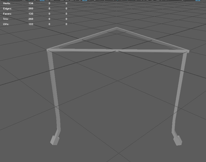
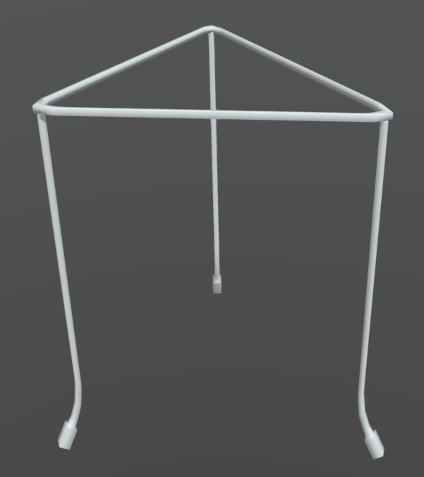
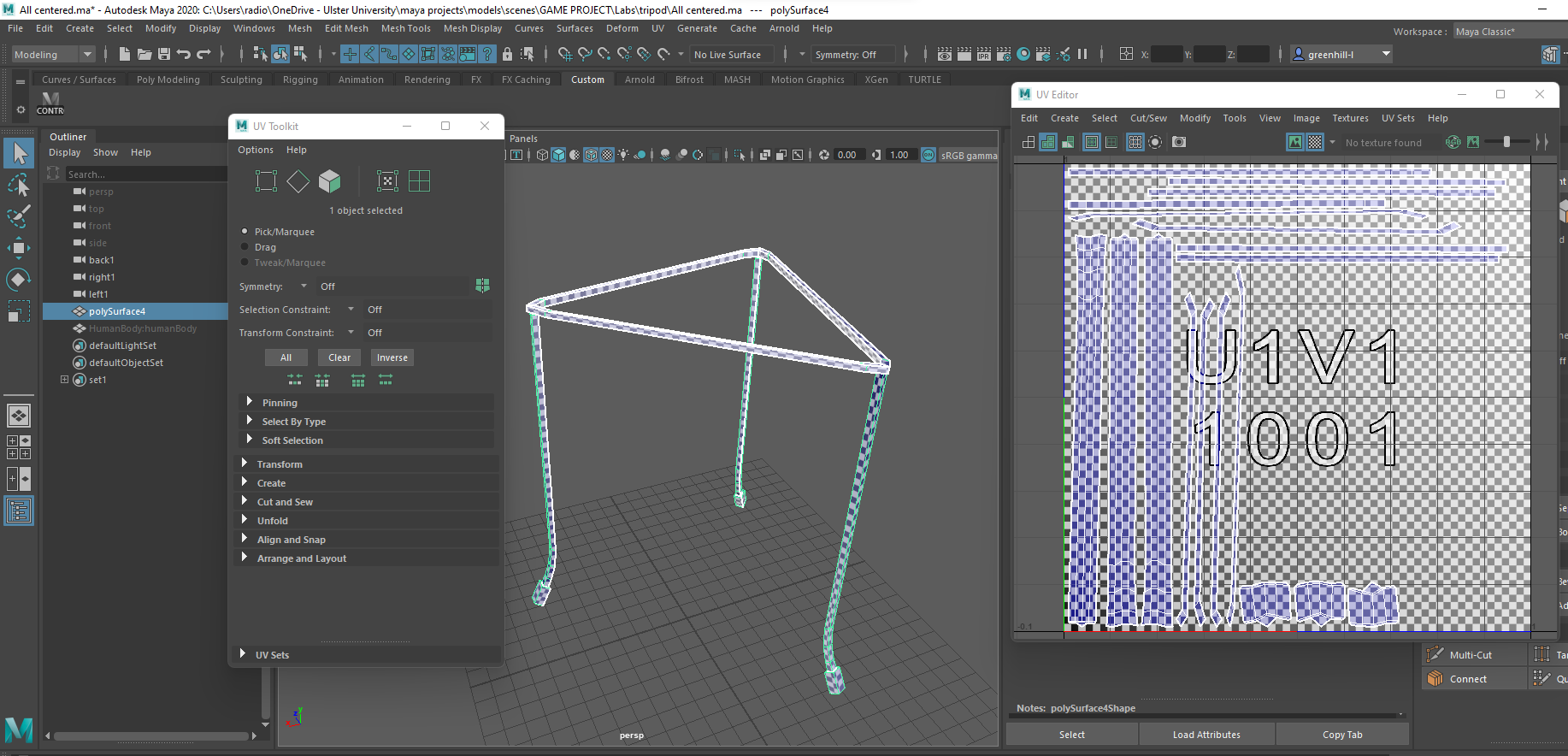
To go along with the Bunsen, i also created a tripod. I realise now looking back on it, a square tripod probably would’ve looked better as I found it a bit difficult making the triangular shape even.
Using the same method as the gas pipe in the previous Bunsen burner model, I created an EP curve spline in the top view mode to create the triangle shape which i converted into polygons by using a face of a cube and extruding it along the splines path, changing divisions and thickness until it suit. To get the finished shape, i selected the edges of the two ends and bridged them which is why the shape is a bit wonky.
To create the legs, I used an elongated cube with multi-cuts placed appropriately at the top to keep shape and bottom to create the bends with soft selection and the little rubber ends on the feet. I then duplicated the original leg twice and rotated the other two to fit under the triangle shape, then smoothed it all and combined all the shapes.
Once smoothed, I cleaned up the poly count quite a bit and moved the model to the middle of the world grid, and placed it just on top, deleting all history and freezing it’s transforms.
I was originally planning to make a burn mat and a gauze to go along with the tripod and Bunsen burner but i just completely forgot and by the time i remembered, it was too late as we had high priority models i had to get done.
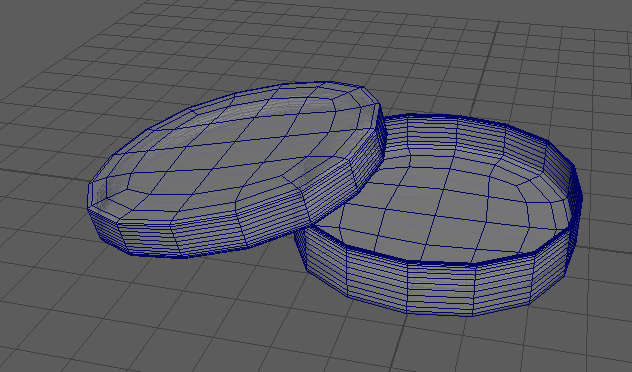
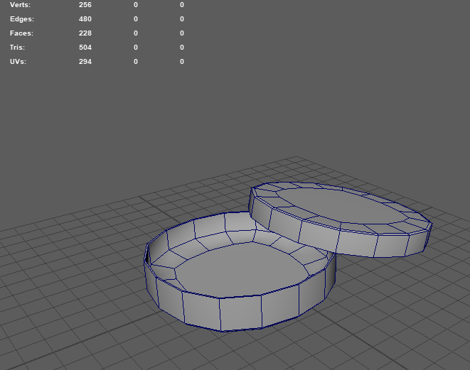
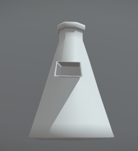
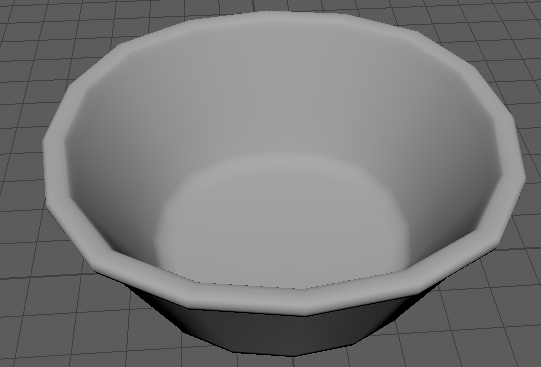
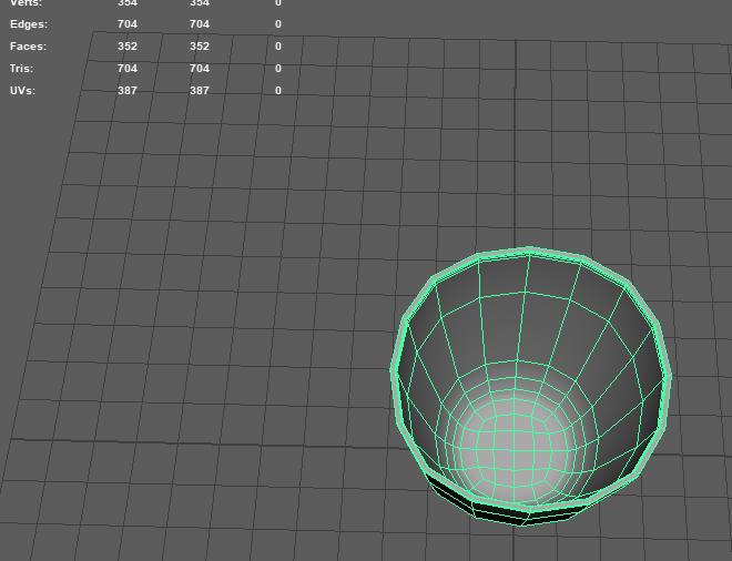
A petri dish would have been essential for the labs, as the narrative we were going for was this abandoned underwater facility was running a sleeper cell experiment, so they’d have to have things like petri dishes and microscopes and the like to study and perfect their chemicals.
Since this object is just two circular discs honestly, it wasn’t that hard to create as all i really did was create a cube, give it multi-cuts, flatten it and smooth it, reduce the poly count, fix the edges i accidentally deleted and then duplicating the first shape then making it slightly bigger ad placing it on a tilt on the bottom dish to create an interesting layout like in the reference.
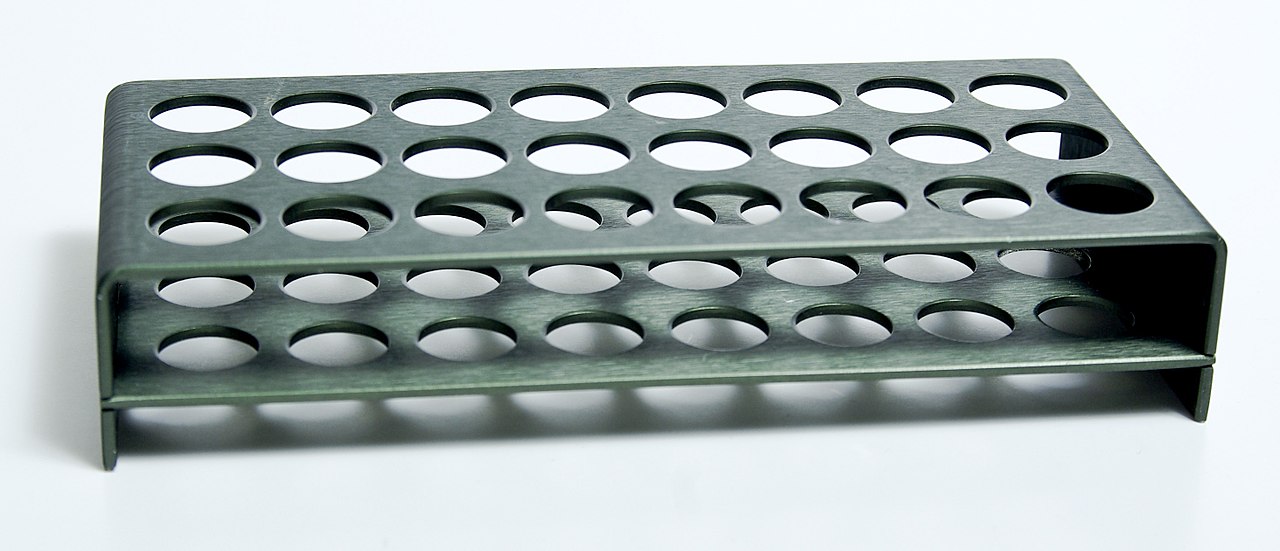
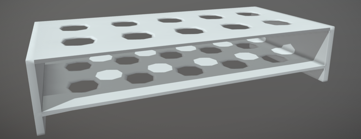
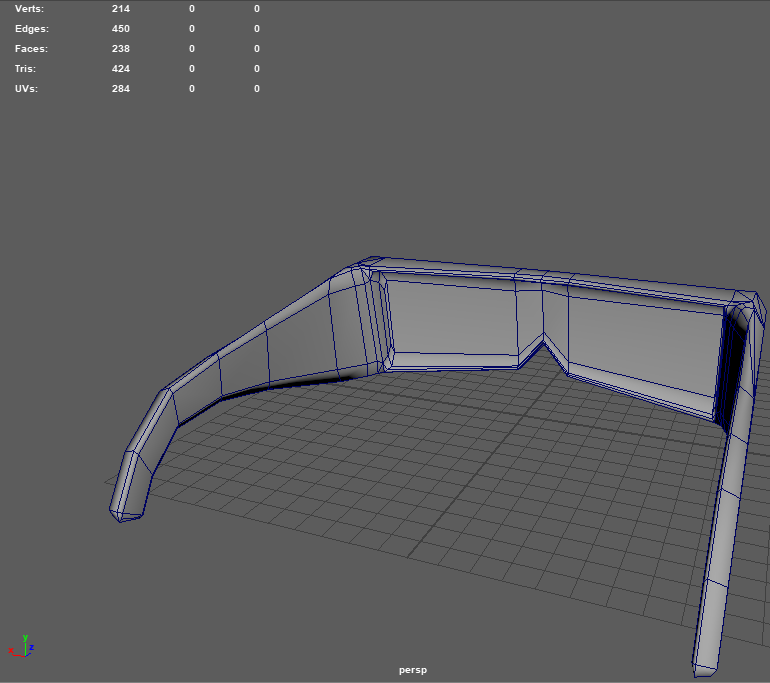
To go along with my test tube from earlier, I also made a test tube stand. I made it in the hopes of being metal so it seemed old and this is also the reason i made it like a little shelf, I thought it helped it look kind of outdated, as i found a couple vintage references of test tube holders that looked like shelves, and i liked the shape of the bottom reference below.
This model was another one i found slightly complicated and had to ask for help from my tutor, Alec, who showed me how to create the holes and make it into an entire shelf, as well as sending over the Maya file he created so i could examine it and use it to learn how exactly everything worked. I had to restart it once though as my attempt before help was a huge failure and a confusing mess.
You’ll be happy to hear this time i did not start with a cube, but with a plane, on which i used the multi-cut tool and the middle mouse button to get accurate lines on one half of the plane, selecting half and deleting it then mirroring the finished side on the vertical axis and doing the same for the horizontal. I then selected all the faces and extruded them at the same time on the y axis to get the thin shelf.
I duplicated the above shelf and bridged the top and bottom faces between the two on both sides, then also extruding the bottom faces on the bottom shelf downwards to make the little legs the whole thing will be held up by.
It was going to need smoothed, so i placed multi-cuts on all the corners and sides i wanted to hold their shape instead of collapsing into the void.
I cleaned up the edges from mostly the bottom shelf and unfortunately with all the holes, this model would have a lot of geometry regardless so it didn’t really change much but as long as its optimized as best as possible and still looks good, the team are happy with it and as am i.
Looking back i now realise i deleted edges i shouldn’t have as ive created N-gons, but it somehow had no problems in texturing that i know of, and the poly count is down quite a fair bit, though i think I was focusing a bit too much on that aspect and thats how i missed this fact.
Apparently this wasn’t my strongest model, as i also used the clean-up tool to automatically fix my problems which i later learned you shouldn’t do, but i wasn’t aware at this point as i only found that out when i was unwrapping everything. At least it runs fine still, and I’ve learned an important lesson for later use.
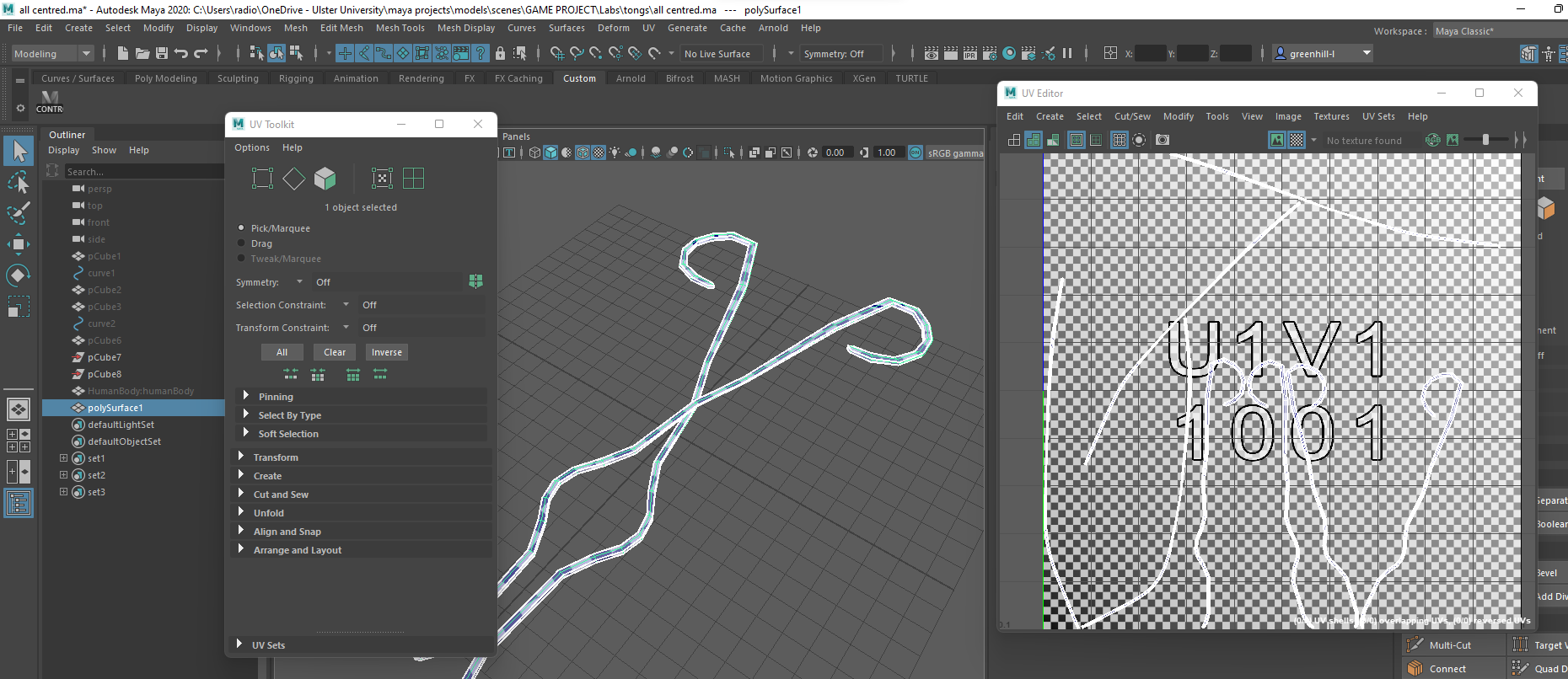
Moving on and going back to the EP curve tool, I went into top view and used a reference of tongs to create a shape similar to the tongs then use the cube face extrusion method to convert it into polygons, duplicating it and rotating it horizontally then combining and smoothing it all.
In the below image, you can see how i first tried to create tongs with a straight line with the more accurate spline sitting to the right of it which i went with instead.
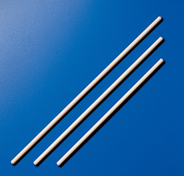
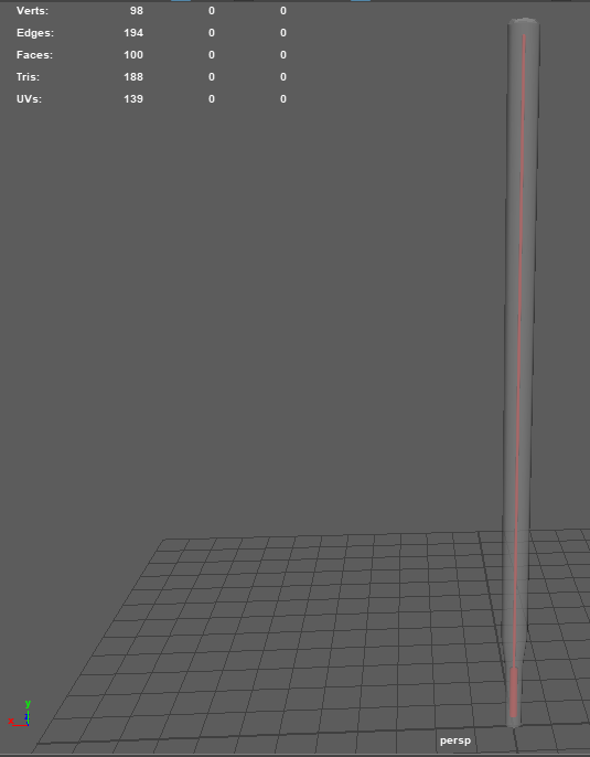
Since we had test tubes, a Bunsen burner and a few flasks, all of which are tall, I decided a glass stirring rod and thermometer would be good things to make so i gathered about one or two references for each as they’re both pretty straight forward.
Starting with the glass stirring rod, I created a cube, scaled it up on the y axis and down on the combination of x and z to make it thinner, gave it a multi-cut at each end, smoothed it then deleted all unnecessary edges and that was it done.
Next, the thermometer, which was made pretty much the same way just with a slope at the bottom and another tube inside for the mercury.
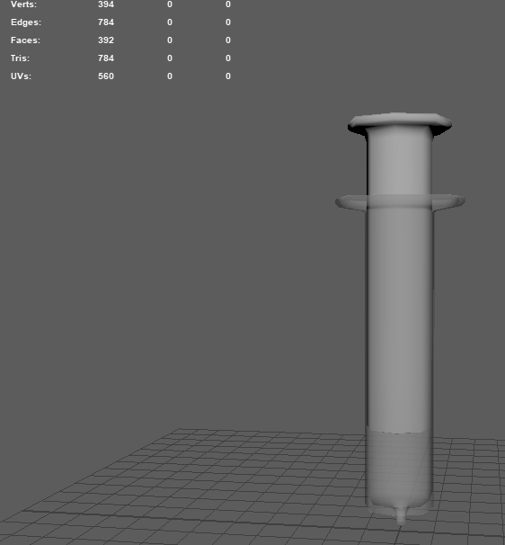
My last model this week was a syringe, which i made in two different parts for top and bottom so if the level designers really wanted to, they could either take the two apart or adjust them to different positions. It was made similarly to everything else as it was a cube elongated, multi-cut and then given a rim and a hole through the middle, the only annoying part was the spout at the bottom.
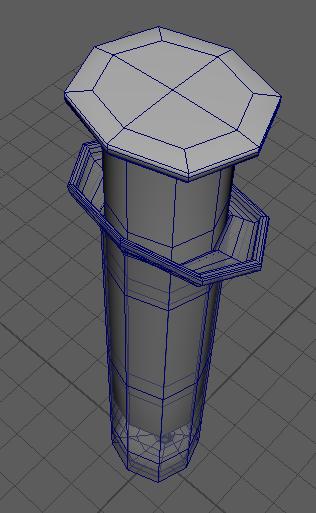
I tried to make the rim a bit more detailed and made a bit of a mess instead at first. I’m not going to lie to you, I’ve absolutely no ide what i did here but i fixed it by deleting it as you’ll see in the following images.
Here I’m just showing off the spout and its structure, made by the bevel, extrude and bridge technique i mentioned earlier for the funnel, funnel flask and a few other things.
Here is a closer look at the fixed model with the proper rim before its smoothed.
I created a simple plunger (the top part) which is used in real life to push down on whatever is inside the tube of the syringe and into the needle by using basically the same method as i did for the bottom part, just without a spout and no dip in the top.
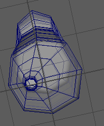
Below you can see how it looks after i’ve smoothed everything.
After smoothing, i cleaned up the geometry and applied a low opacity lambert material for a plastic see through look on the bottom tube part.
After our room showcase, the tutors gave us the go ahead to start planning a list of assets we’d need for the real thing, start dealing with roles and get together with our group to discuss our plans for creatues/monsters and how we wanted the game to work.
In Discord, we set up a few different channels so we could easier find the corresponding information under the channel name, e.g reference ideas and designs went into “references”, game narrative went into “ideas”, etc. This made trying to plan everything a lot easier as we were encouraging group members to use the appropriate channels when discussing ideas and topics. We also had roles that each member could assign themselves, so the other group members would know who was responsible for what and it was easier to contact a certain role.
We began thinking about the outline of the narrative, using the Miro board to pin down some loose ideas, we all seemed to agree on the player character being a reporter/journalist in the early 2000’s who was sent to investigate the remains of an underwater experimental facility, led by the Russians in the 60s. We had talked about hallucinations that where shown by having the player see things that weren’t showing up on the camera, though there was a bit of a worry about how we were going to achieve this, and monsters that could potentially be chasing or hunting you down, unsure of whether we wanted them to actually physically hurt the player or not. Karl came up with the idea of a gasmask that the player could equip due to a toxic gas tainting the air which is what made the reporter start to see things in the first place, and that when the gasmask was on, the player slowly stopped seeing the hallucinations for a while, kind of similar to the fredbear mask in Five Nights at Freddys. On the topic of the gas, we started to question whether it should be the thing that ultimately kills the player in the end and whether ee should give a whole death cutscene, which then brought and in the idea of a little girl killing you with a jumpscare.
Another idea we had was adding a “sanity bar” to the corner so that you had a goal to work towards but also had limitations. Branching off this idea, we added a pill bottle and thought something like a torch would be cool to shine at the monsters and scare them away or kill them. We talked for a bit longer about how the bar would work and the Game Design students were chatting about how they’d go about actually creating it and making it run, discussing a “wheel selection” toggle to store and select the items you have, which then also led on to brainstorming ideas for items to pick up along the way such as notes, key cards, letters, etc to help piece the story together and also help the player navigate through the levels.
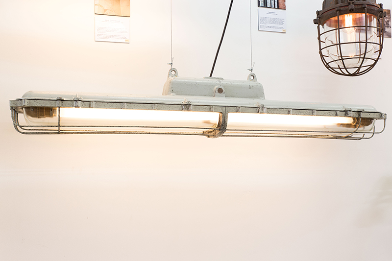
As for the asset list, we managed to scrounge up a small one for each modeller, I had to restart my light and make it look more 60s as the group thought the cage and iron on my light didn’t fit well, so I found a few reference images by searching up “60s school lab” as I know they had some pretty cool lights back then, and found a cool fluorescent hanging light, sort of like my first attempt but lighter and more exposed. Halfway through modelling though I realised I didn’t like it and went back to looking for references, finding an old iron soviet Russia fluorescent light, which of course fit perfectly with everything we were going for, so I decided to get as many references of that as I could find (not many ._.) and restart the model again.
Below are my references, the first two are for the light i scrapped followed by a soviet fluorescent light i went with in the end.
Same as the last light, I started off with a cube and just built on that, using the toolkit that came with maya and a few shortcut keys I’d learned throughout my own research and the assignment from last year. I followed the details in the reference as best as I could, giving the light a flat surface on the top to easily mount to the ceiling, curving down into the case over the two bulbs that were connected to the main body. The light tubes were made exactly the same way as last time, only I added in the “joint” that connects them to the body so they didn’t look like they were floating. After I added clasps to the sides with some really awkward polygon manoeuvring and bridging, I was ready to separate my model into different materials and export it for substance painter.
Created the two main body parts: the light casing and the metal part that connects to the ceiling.
Created a cylinder polygon primitive, scaled it to fit the light casing, and reduced it’s subdivisions to get a lowpoly cylinder, duplicated it and moved it over, which I later smooth to become round tubes for the lights.
I used a cube to make the rim of the light which would go between the light casing and the metal ceiling connector.
Here i put it all together to see how well it fit and where everything needed to be placed in accordance to one another.
Next, i added a clasp which i created from extruding the faces on the metal ceiling connector and the light casing, which was a bit confusing at first but i think it turned out alright.
Selecting half the model and hiding the lid, i deleted it and mirrored the side with the finished clasp so it was identical on both sides.
Creating a vertical loop cut through the middle of the model, i selected one half and deleted it again, then mirroring the half with the finished clasps. Now i have all four clasps in identical places and i unhide the lid.
Here is my model before smoothed with a material applied to the light casing to appear more glassy as in real life.
Below is my model now smoothed and reduced, it’s a bit messy but I didn’t know back then that was the case and thought it was ok since the poly count was low.
The following images are when i created the joints for the lights to connect to the body of the light, followed by materials applied in Maya and different angles of the finished model.
Below is the model UV unwrapped by selecting edges and cutting where i ant the seams to go, which is usually on the top and bottom of each shape so each side has its own shell as this will help the texture display better and less contorted.
Texturing:
Bringing my model into Substance Painter, I started like last time, laying down all the base colours and adding a new layer for each new texture such as the iron, glass and plastic for the body, lights and casing and then another 4 or 5 for the rust, grime and scratches as I like the work in layers, I find it easier to correct a mistake this way as it wont affect anything above or below what I’ve already painted, or what the industry likes to call “non destructive editing”. I wanted to sell the look that this light had been underwater, corroding away with rust and dirt in the air and later, barely working as I planned to animate a flicker effect.
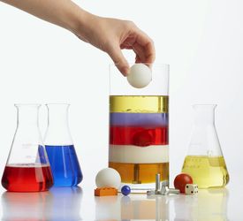
From our task last week, my group managed to piece together a general idea of what we wanted our game to look and feel like. We chose realism as our style aim as its proven to be more successful in horror than things like cartoony styles, so we chose to make realistic models for our “show room”. I took on the task of making a light, which I wanted to animate swaying back and forth gently, creaking and with a flickering light.
The thought process:
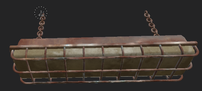
I was a little confused at first with what we were being told to do, but luckily my teammates are very understanding and were able to explain to me so I could proceed to starting my work. I told them i was going to go for a light, since one of the examples they gave me was about a wire sparking, it just made me think of a flickering light. I reckoned in horror games like this, especially in abandoned places and old sites, they usually had a fluorescent light that would buzz and flicker to make the atmosphere heavier and break the silence with an unsettling hum. Just typing in “fluorescent light 60s” didn’t really get me too far as it wasn’t really anything I thought would work in our atmosphere, so I then started searching “underwater light 60s” and found some pretty cool lights known as “crocodile” lights that I figured would suit well with the underwater atmosphere as they’re heavy iron with hard casing and a cage. With this light now in mind, I was happy enough to begin creating for our set.
Once I gathered some refences of this light type at different angles, I also checked to see how other people have gone about modelling this kind of thing, examining how everyone approached the light bulb inside the “casing”, how much or how little detail did they put into it, what kinds of lights were they focusing on, that sort of thing. It also helped looking at these models to find out small details I couldn’t see too well on the reference images I gathered. Now happy with what I was modelling, I drew a very terrible rough look on my phone and opened Maya to get started.
The making:
I modelled everything starting out with a cube, as this is something I picked up in first year, and if I need something like a sphere or cylinder, I use the smooth tool. For cases like how I created the light bulb strips, I spawned a cylinder polygon and reduced the subdivisions so it was more so a pentagon, changed the dimensions of the axis to be longer and a little wider, then smoothed it for a rounder look. When creating the light “body” I also started off with just a cube, making multi-cuts, extrusions and bevels where necessary then manually selecting and deleting edge loops to reduce the polygon count. The cage part was a little annoying at first, as I’d always usually tried to avoid complicated shapes such as curves and bends because I didn’t really understand how to do them. I had to watch a tutorial for how to use the “bend” deformer but I was still confused, so in the end I spawned a cube, used the multi-cut tool to give it subdivisions and then pressed B on my keyboard to get the soft-selection tool, rotating and moving each section little by little until I was happy with the bar. To make it easier on myself, I placed a cut directly in the middle of the bar, selected the left half and deleted it so I could then mirror the right side so I had an even shape. I then duplicated the shape around 6 times and placed each a little further back, giving an even layout to all the bars.
I made chains for the light, which I intended to have lightly swinging the light, by spawning in a cube, selecting the left face and using ctrl+E on my keyboard to extrude the face, rotating it slightly and moving it up to the left, then extruding that face, rotating and moving it and extruding that face and so on until I had a circle of links. Using the same technique as the bars, I selected one half of the circle and deleted the faces, allowing me to use the mirror tool to get a completely symmetrical look. Once happy with the circle, I duplicated it and turned it sideways, placing the top of this new loop on the bottom of the previous, creating what was starting to look like a chain link. I did this a few more times, duplicating a link, rotating it to face the correct way, positioning it and once I had about 6 or so links in the chain, I selected all the links and used the combine tool, edit>delete all>history and freezing their transformations once I positioned them on the light. I then duplicated the entire chain and shifted it over to the other side of the light.
Texturing:
With my model now finished and cleaned up, I exported it using the game exporter plug-in in Maya and saved it into an “exports” folder where I’d later put the rest of the games models for easy access. Switching to Substance Painter, I got a few references of rust and wear and tear from google and started painting the base colours of the light, giving the outside an iron texture, the casing a kind of plastic feel and making the fluorescent lights glass. I messed around for a bit, layering colours and textures on top of each other, just doing what I felt looked good then moved onto the rust. For the rust I had about 3 or 4 different layers, with the base colours, the actual texture, more grain, and then small details such as scratches and peeling. Again I just kind of kept the reference images in mind as to where most rust would gather and how it spreads, then just painted in what I thought looked good and scientifically correct.
Other things we had to have done by this week were deciding on a group name (or at least a rough template), have a logo thought out if possible, and team roles, all set out in a handy image sent by the tutors.
The first message was sent by Karl but his name got cut off as my screen isn’t big enough, but here is a screenshot of us discussing possible team names.
In the end Karl was the one who actually made the name we stuck with, Scaredy Cat Studios.
We then started talking about possible logo ideas, with me suggesting we go with a hissing cat thats all puffed up, to go with the general idea of fear.
In the end, Tori drew out an idea for the logo and we all liked it so we stuck with it and used it as our Discord server picture to make it feel more official.
By this stage we’d also thought about a name for the game, going with names like “Mendacium” or similar kind of sounding names until we remembered how we’d talked about Sciophobia being the strong disliking or fear of shadows and we thought that fit our game idea really well, so was born the name for our game.
Image credit to team mate Joe from games design who created the above title slide for our presentation and the below fake game cover and reveal trailers.
I decided to make a separate post for the ideas section of our project as we had a whole Miro board dedicated to possible genres and story routes, as seen below.
[MIRO BOARD LINK OR IMAGES HERE]
Our game was going to be a psychological horror with a rough idea of exploration with hallucinations, further branching out into the wheres, whys and whats for our atmosphere and storylines.
In the beginning, we were talking about shows, games and real world happenings that had inspired us and to try fit together a general feel of what everyone was going for to get us all on the same page. Part of this was talking about the art style which we all pretty much immediately agreed on realism as it made horror feel more threatening and gave a sense of unease to the player as they can relate it to the real world
Our first assignment for this semester back was to team up with the Games Design students and create a fully playable game with a goal, objectives and at least somewhat of a storyline. Each department had to take care of their respective side of things, but were allowed and encouraged to help wherever they could, as it gave experience and broadened horizons.
Work was judged individually depending on how much effort each student has seemed to put into the project. This was portrayed through blogs, weekly presentations on progress, one to one or group meetings with the tutors and of course the resulting work that they have to display. Animation students were dealing with the art side of things such as backgrounds, art, hard surface modelling, animation, etc while Game students were focusing on the game coding, scripts, AI, all that sort of stuff.
Before this project had began, we were all sent out a short form to fill in on what roles we were happy with taking on for the project and which we’d rather not. I was happy with pretty much anything except for lighting and backgrounds as I don’t really understand how to effectively do either, which tells me I should definitely set some time aside and work on that in the future. My main two topics I chose that interested me were modelling and animating, rigging was also in the same category as animating but I was a little worried about that since I’d only rigged a bird feet model I’d previously created for a short in first year.
Fast forward to meeting our groups, I haven’t been able to get in due to no travel availability but I make sure to keep my phone by me on loud at all times so I can quickly get updates and respond to the group as we communicate via Discord and try to hold meetings as frequently as possible. To get a feel for the kind of work our teammates were used to doing and what they could provide to the project, we all sent in our portfolios and show reels for the others to have a look. Seeing as though I wasn’t in, they contacted me on Discord where I sent a link to my blog portfolio, my showreel and my Sketchfab profile, making sure I was giving them all the evidence they needed to see what I was capable of and where I’d be best suited. Two of the games students, Karl and Joe, sent their portfolios for me to look at too and their work was really impressive! Seeing what they’d already done made me really excited to start working on the project and combine all our skills to come out with a really good game.
Later on in the day I was informed that the class had been talking about the general brief of the project and that we had been set a homework to talk about the genre and feel of the game we were working towards and to create a “room” which would have a piece of work done by each group member to showcase what genre/feel we had chosen. We had decided that a group VC meeting would be best in order to fill everyone in on what had been talked about in class and to further discuss our game ideas, though everyone at this point had agreed on a horror genre which later developed into a psychological horror in which the player is haunted by hallucinations that they can’t pick up on the camera and a vague idea that there would be a girl chasing the player.


 unfortunately this photo wasn’t great resolution but it did the job.